Table of Contents
Advertisement
Quick Links
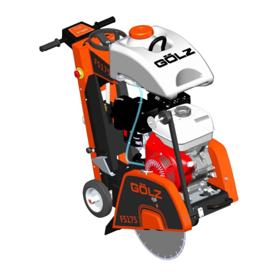
FS175
Original-Bedienungsanleitung und Ersatzteilliste
DE
Fugenschneider
Original operating instruction and spare parts list
GB
Floor saw
Originale du mode d'emploi et liste des pièces de rechange
FR
Scie de sol
Origineel Gebruiksaanwijzing en Reservedelenlijst
NL
Vloerenzaagmachine
ZN der Bedienungsanleitung:
Erstellt am:
Erstellt von:
Datei:
®
GÖLZ
GmbH
Dommersbach 51
D-53940 Hellenthal
Telefon: +49 (0) 2482 12 200 / Telefax: +49 (0) 2482 12 222
E-Mail: info@goelz.de / Internet: www.goelz.de
5007287-01
07 / 2016
Sabrina Linden
K:\KDV\5007xxx\5007287-Bedienungsanleitung\
5007287-01-Bedienungsanleitung-DE-GB-FR-NL.doc
- 1-
®
5007287-01
BA-DE-GB-FR-NL
Advertisement
Table of Contents

Subscribe to Our Youtube Channel
Summary of Contents for GÖLZ FS175
- Page 1 ® FS175 Original-Bedienungsanleitung und Ersatzteilliste Fugenschneider Original operating instruction and spare parts list Floor saw Originale du mode d’emploi et liste des pièces de rechange Scie de sol Origineel Gebruiksaanwijzing en Reservedelenlijst Vloerenzaagmachine ZN der Bedienungsanleitung: 5007287-01 Erstellt am: 07 / 2016...
- Page 2 ® FS175 Alle Rechte nach DIN ISO 16016 vorbehalten. Onder voorbehoud van alle rechten volgens DIN ISO Kein Teil dieses Dokuments (Bedienungs- 16016. anleitung und Ersatzteilliste) darf ohne vorherige Geen enkel deel van dit document schriftliche Genehmigung durch die (gebruiksaanwijzing en reservedelenlijst) mag zonder voorafgaande schriftelijke goedkeuring van ®...
- Page 3 ® FS175 EG-KONFORMITÄTS- EC-DECLARATION OF DECLARATION DE EG-KONFORMITEITS- ERKLÄRUNG CONFORMITY CONFORMITE DE LA CE VERKARING Die Firma Manufacturer La Société De Firma ® GÖLZ GmbH Dommersbach 51, D-53940 Hellenthal Tel.: +49 (0) 2482 12 200 / Fax: +49 (0) 2482 12 222 erklärt in alleiniger Verant-...
-
Page 4: Table Of Contents
® FS175 Preface ............................. 22 Warning signs and symbols ......................22 Machine description ......................23 Intended use-description ....................23 Technical data ........................23 Shipment and provided accessory ..................23 Main parts .......................... 23 Operating elements ......................24 Safety devices ........................24 Basic safety instructions ..................... -
Page 5: Machine Description
Operate the machine only using tools in accordance • Floor saw FS175 without blade with the manufacturer’s instruction. Using other tools is • Wrench SW 13,17, 30, 32 considered contrary to its designated use. The manufacturer cannot be held liable for any damage •... -
Page 6: Operating Elements
® FS175 Operating elements 1. Hand wheel - raising and lowering 2. Depth control Safety devices Danger: During cutting or displacing The base frame (1+2) is the basis for the floor saw. All the machine, all safety devices shown other components are built on the base frame. -
Page 7: Intended Use
® FS175 In addition to this operating manual, all other generally Attention: Contains instructions which applicable legal and other mandatory regulations must be strictly observed to prevent relevant to accident prevention and environmental damage from the unit and the operator! -
Page 8: Selection And Qualification Of Person
® FS175 GmbH prior approval! This also applies to the installation obstacles in the working and travelling area, the soil and adjustment of safety devices as well as to welding bearing capacity and any barriers separating the and cutting work on supporting structures. -
Page 9: Special Work Related To The Maintenance And Repair Of The Machine
® FS175 Special work related to the Any safety devices removed for set-up, maintenance or repair purposes must be refitted and checked maintenance and repair of the immediately upon completion of the maintenance and machine repair work. Ensure that all consumables and replaced parts are disposed of safely and with minimum environmental impact. -
Page 10: Gas, Dust, Steam, Smoke
® FS175 Protective installations with fault-current protection Be careful when handling hot consumables (risk of units used in non-stationary equipment must be burning or scalding) particularly at liquid temperatures checked for correct operation at least once a month by above 60° C, avoid any skin contact with these liquids! a properly instructed person. -
Page 11: 2.13 Store
® FS175 Installation Attention: Check that all parts of the machine well fastened before Place the machine on an even, firm and stable ground. transporting. Before transporting the blade must be removed! Have the working area well lightened. Keep the For loading, only use lifting gear and working area clean, cluttered areas invite injuries. -
Page 12: 3.3.1 Mounting The Blade
® FS175 3.3.1 Mounting the blade Secure the blade and outer flange with fixing nut • SW30/SW32. Fit the blade guard again and secure it with Blade mounting: • screws.(3) Mount the blade to the manufacturer’s odds • (Observe the min. flange-Ø; use only original Danger: It is not allowed to operate the screws or nuts). -
Page 13: Operation
® FS175 valve (1) is closed (ball valve lever in 90° -position to Danger: The sound pressure may the water flow). exceed 85 dB(A)! For cutting open the ball valve (1) (ball valve lever in the water flow position). Appropriate to the application of the machine it could be necessary to wear further protective equipment. -
Page 14: Cutting Operation
® FS175 Completely raise the machine until the brake engages (blade may have no ground contact). Engine switch is in ON position (1). Emergency switch is unlock (2).Start the engine as described in the engines manual (3). Cutting operation Danger:... -
Page 15: Lubricating Chart
® FS175 In the case when the eccentric is moved to its farthest position while the belt is still not stressed, remove the eccentric; assemble it in another hole on upper Visual chassis, then start to adjust the belt stress again (1,2,... -
Page 16: Removal
® FS175 Removal Problem Cause Remedy Engine Slacken all screws. Depending on the size of the bush Bad engine Dirty air cleaner Clean remove one or two. After oiling point and thread of performance! grub screws or under head and thread of cap screws, insert them into the jacking off holie(s) in bush.


Need help?
Do you have a question about the FS175 and is the answer not in the manual?
Questions and answers