
Subscribe to Our Youtube Channel
Related Manuals for GÖLZ FS 250 B


Summary of Contents for GÖLZ FS 250 B
- Page 1 FLOOR SAW FS 250 B 0282 250 0958/12.05 r:\technik\techdoku\englisch\fs\250b\2000958\02822500958_02_14-12-05.indd...
- Page 2 Telefax: (02482) 12135 CE-Declaration of Conformity We declare, the product Name: FLOOR SAW Manufacturer: GÖLZ Type: FS 250 B Serial number: __________ is in conformity with the Directives 98/37/EC 89/336/EWG i.d.F. 93/68/EWG 2000/14/EC as well as with the standards EN 13682:2001 EN 13309:2000;...
-
Page 3: Table Of Contents
Contents 1. Basic informations ..........4 2. Fundamental safety instructions ......4 3. Description............9 4. Transport ............. 11 5. Installation and operation........12 6. Maintenance............16 7. Troubleshooting ..........19 8. Spare parts list ........... 21 9. Connection diagram........... 40 All rights reserved! We endeavour continuously to improve the quality of our products and adapt them to the highest technical standards. -
Page 4: Basic Informations
1. Basic informations Thanks for choosing a GÖLZ-product. This operating instruction is designed to familiarize the user with the machine and its designated use. The operating instruction contains important information on how to operate the machine safely, properly and most efficiently. Observing these instructions helps to avoid danger, to reduce repair costs and downtimes and to increase the reliability and life of the machine. - Page 5 2.2 Basic operation and designated use of the machine The machine has been built in accordance with state-of-the-art standards and the recognized safety rules. Nevertheless, its use may constitute a risk to life and limb of the user or of third parties, or cause damage to the machine and to other material property.
- Page 6 Replace hydraulic hoses within stipulated and appropriate intervals even if no safety-relevant defects have been detected. Adhere to prescribed intervals or those specified in the operating instructions for routine checks and inspections! For the execution of maintenance work, tools and workshop equipment adapted to the task on hand are absolutely indispensable.
- Page 7 Brief operating personnel before beginning special operations and maintenance work, and appoint a person to supervise the activities. In any work concerning the operation, conversion or adjustment of the machine and its safety-oriented devices or any work related to maintenance, inspection and repair, always observe the start-up and shut- down procedures set out in the operating instructions and the information on maintenance work.
- Page 8 Gas, dust, steam, smoke Carry out welding, flame-cutting and grinding work on the machine only if this has been expressly author- ized, as there may be a risk of explosion and fire. Before carrying out welding, flame-cutting and grinding operations, clean the machine and its surroundings from dust and other inflammable substances and make sure that the premises are adequately ventilated (risk of explosion).
-
Page 9: Description
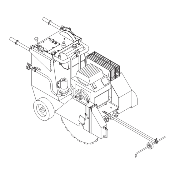
3. Description 3.1 Intended use-description Operate the floor saw only using tools in accordance with the manufacturer’s instruction. Using other tools is considered contrary to its designated use. The manufacturer cannot be held liable for any dam- age resulting from such use. The risk of such misuse lies entirely with the user. Operate petrol driven floor saws only with motor fuel the engine manufacturer specifies. - Page 10 Maintenance flap (rear side) Muffler guard V-belt guard Flange guard Blade guard for max. blade size of 800 mm - 31.5 in. 3.4 Technical data Max. cutting depth: 280 mm - 8.65 in. Max. blade-Ø: 800 mm - 31.5 in. Blade shaft size: Ø...
-
Page 11: Transport
Weight empty: approx. 280 kg - 616 lbs. Kerb weight: approx. 292 kg - 643 lbs. (filled fuel tank and mounted blade Ø 750 mm - 23.6 in.) Sound power level: 106 dB(A) Sound pressure level: 90 dB(A) 4. Transport Injury hazard: Injury hazard: Down Injury hazard: Down... -
Page 12: Installation And Operation
5. Installation and operation 5.1 Installation Place the floor saw on an even, firm and stable ground. Have the working area well lightened. Keep the working area clean, cluttered areas invite injuries. Operating the floor saw on enclosed premises, make sure that there is sufficient ventilation. - Page 13 Remove the toggle of the main switch in the control panel or disconnect the power supply before mount- ing or changing blade. Information: Clean all fastening devices of the blade (flanges, thread of the blade shaft, screws and nuts) before mounting the blade! The working area is reserved only for the operator.
- Page 14 Danger: Down coming parts at the building site can cause injuries to the operator! Mounting the blade Remove the toggle of the main switch in the control panel before mounting the blade. Mount a blade with arbor hole of 25.4 mm - 1 in. and a max. blade size of Ø 600 mm - 23.6 in.
- Page 15 Cutting operation Control panel Traversing gear ON-OFF Control panel Lifting Lowering Foreward - Reverse Depth control Main switch toggle Choke Engine starter Water pump ON-OFF Charge indicator lamp Oil-pressure indicator lamp (without function) Danger: Operating with too high feed the floor saw might rise out of cut! In emergency situations shut down the floor saw immediately by turning the toggle (6) of the main switch! Warning: Before switching on the traversing gear the lever (3) must be defi-...
-
Page 16: Maintenance
6. Maintenance 6.1 General Information: Unconditional observe the owner’s manual of the engine manu- facturer, which is added! Information: Clean the floor saw after every operation. Observe local environ- mental regulations! Attention: Drain the water pump if frost will appear! Attention: Work on hydraulic equipment may be carried out only by persons having special knowledge and experience in hydraulic systems! Attention: When handling oil, grease and other chemical substances, observe... - Page 17 Danger: Unintentional striking back of the V-belt tensioner can cause in pinching injuries to the operator! 6.3 Lubrication chart Oil change after 1000 working Hydraulic power unit: hours or once a year0,9 Litre - 55 cu. in. ATF Static displacement drive: Oil change after 500 working hours or once a year 0,65 Litre - 40 cu.
- Page 18 After 20 working hours grease Spindle shaft bearings: with heat resistance fat Undercarriage bearings: After 20 working hours grease with heat resistance fat Hydraulic cylinder bolts: Clean from time to time and grease with some drops of oil Clean from time to time and Front axle: grease with some drops of oil...
-
Page 19: Troubleshooting
7. Troubleshooting Attention: In the event of changes in the behaviour of the floor saw during operation, stop the machine immediately and report the malfunction to the competent authority/person! PROBLEM CAUSE REMEDY Engine Fuel tank empty Refill Engine does not run! Fuel lines obstructed Clean fuel lines For further troubleshooting refer to the owner’s manual of the engine manufacturer,... - Page 20 Wearing parts for contruction devices mentioned in the operating manual such as drilling and sawing machines Wearing parts are the parts subject to operation-related (natural) wear during proper use of the device. The wearing time cannot be uniformly defined, and differs according to the intensity of use.
-
Page 21: Spare Parts List
8. Spare parts list Always indicate: machine/model/serial number item number and description of the spare part amount of spare parts desired full address goods to be sent by regular mail, express, etc. Zeichenerklärung Key to symbols Légende = bestehend aus Pos. = consisting of pos. - Page 22 Ersatzteile für Maschinen neuerer Bauart - Spare parts for sequential models - Pièces de rechange pour machines de dernier construction...
- Page 23 Pos. Type Qty. Benennung - Part name - Désignation 0282 250 0690 Klemmfeder - Clamping device - dispositif de serrage 0282 250 0657 Schutzhaube Keilriemen - V-belt guard - Capot de protection pour courroie 0282 250 0759 Schutzhaube Flansch - Flange guard - Capot de protection pour flasque de fixation 0282 250 0768 Versteifung Bodenblech - Stiffening plate - Tôle de plaque...
- Page 24 Ersatzteile für Maschinen neuerer Bauart - Spare parts for sequential models - Pièces de rechange pour machines de dernier construction...
- Page 25 Pos. Type Qty. Benennung - Part name - Désignation 0282 250 0790 Schutzhaube kpl. - Blade guard assy. - Capot de protection complet - ¡ Pos. 29 -46 0282 250 0757 Schutzhaube hinten - Blade guard - Capot de protection 0282 250 0798 Schutzhaube hinten - Blade guard - Capot de protection - â...
- Page 26 Ersatzteile für Maschinen neuerer Bauart - Spare parts for sequential models - Pièces de rechange pour machines de dernier construction...
- Page 27 Pos. Type Qty. Benennung - Part name - Désignation 0282 250 0750 Bedienpult - Control panel - Panneau 0282 200 0500 Wasserpumpe - Water pump - Pompe à eau Ò 0295 000 3503 Schraube - Screw - Vis - M6x30 DIN 7380 0282 250 0660 Scheibe - Washer - Rondelle - A6,4 DIN 125 0282 250 0605...
- Page 28 Ersatzteile für Maschinen neuerer Bauart - Spare parts for sequential models - Pièces de rechange pour machines de dernier construction...
- Page 29 Pos. Type Qty. Benennung - Part name - Désignation 0282 250 0782 Transportbügel - Lifting bow 0285 300 0015 Mutter - Nut - Ecrou - M12 DIN 982 0282 250 0663 Scheibe - Washer - Rondelle - A13 DIN 125 0295 000 3515 Schraube - Screw - Vis - M12x35 DIN 7380 0295 000 0170...
- Page 30 Ersatzteile für Maschinen älterer Bauart - Spare parts for previous models - Pièces de rechange pour machines d´ancienne construction...
- Page 31 Pos. Type Qty. Benennung - Part name - Désignation 0282 450 0513 Winkel - Elbow - Raccord courbé - XEVW 10LV 0291 1041 T-Stück - T-piece - Pièce en T - XEVT 10LV 0282 250 0650 Drosselrückschlagventil - Flow control valve - Soupape étranglement 0291 1018 Nippel - Fitting - Nipple - GE 10L-1/8“...
- Page 32 Ersatzteile für Maschinen älterer Bauart - Spare parts for previous models - Pièces de rechange pour machines d´ancienne construction...
- Page 33 Pos. Type Qty. Benennung - Part name - Désignation 0282 250 0727 Knebel - Toggle - Garrot 0282 200 0605 Chokezug - Cords - Tirage 0282 250 0482 Motorüberwachung - Control panel - Tableau de commande 0296 000 0114 Schraube - Screw - Vis - M5x8 DIN 7991 0282 250 0426 Drucktaster - Touch contact - Touche à...
- Page 35 Pos. Type Qty. Benennung - Part name - Désignation 0282 250 0567 Motor - Engine - Moteur -Kohler CH 25 S 0282 250 0572 Keilriemenscheibe - V-belt pulley - Poulie à gorge pour courroie trapézoidale - DW71x7SPZ 0282 250 0598 Scheibe - Washer - Rondelle - A18,5 DIN 7349 0282 250 0611 Schraube - Screw - Vis -5/8“-18G UNFx1-1/2 DIN 933...
- Page 37 Pos. Type(*) Qty. Benennung - Part name - Désignation 0282 250 0170 Scheibenfeder - Woodruff key - Clavette disque - 3x5 DIN 6888 M788046 Dichtung - Seal - Garniture Ò 0282 250 0501 Antriebsachse - Driving axle - Arbre primaire - Mod.1352 0282 250 0168 Hydrostatisches Getriebe - Static displacement drive - Commande hydrostatiques...
- Page 39 Pos. Type Qty. Benennung - Part name - Désignation 0282 300 0008 Splint - Split pin - Goupille fendue - 6,3x40 DIN 94 0282 250 0761 Fahrwerk - Undercarriage - Chariot 0281 073 0049 Scheibe - Washer - Rondelle - A25,0 DIN 125 0282 065 0019 Stehlager - Pedestal bearing - Chaise palier - UCP 205-D25 Ò...
-
Page 40: Connection Diagram
9. Connection diagram Cylinder...
Need help?
Do you have a question about the FS 250 B and is the answer not in the manual?
Questions and answers