
Related Manuals for GÖLZ Bridge Saw


Summary of Contents for GÖLZ Bridge Saw
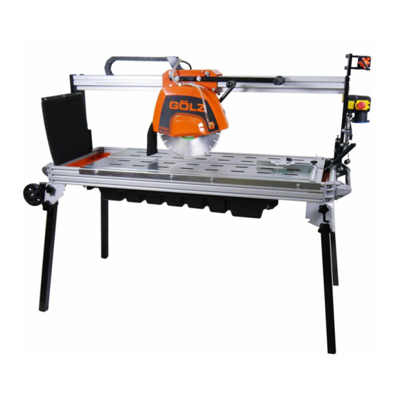
- Page 1 Translation of the Original Operating Manual Bridge Saw – GS 350A-120 Read operating manual before starting any work! Keep the operating manual for future use! 1 / 86...
- Page 2 2 / 86...
- Page 3 Content Revision Date Chapter Reason of change Person responsible 03-19 Recreation Design 02-21 12.4.2 Wheel set changed Design Revision status: 2021-02 Serial number: © Gölz GmbH Dommersbach 51 D- 53940 Hellenthal Tel.: +49 (0)2482 – 12 200 Fax: +49 (0)2482 – 12 222 E-Mail: info@goelz.de Internet: www.goelz.de 3 / 86...
- Page 4 Content Content 1 Content ................................. 4 2 General information ............................ 7 Operating manual ..........................7 Symbols, abbreviations, terms......................7 Explanation of symbols ........................7 Limitation of liability ........................... 8 Customer Service ..........................9 Copyright............................9 3 Safety ................................10 Appropriate use ..........................10 Reasonably foreseeable misuse ....................
- Page 5 Content Connect ............................29 Initial commissioning and acceptance, general ................29 7.4.1 Measures before initial commissioning ................30 7.4.1.1 Mounting the cut-off wheel ..................30 7.4.1.2 Filling the water sump ....................30 8 Operating ..............................32 Safety instructions for operation ..................... 32 Intended working position of the operator ..................
- Page 6 Content 12.4 Optional accessories ........................80 12.4.1 Roll jib ..........................80 12.4.2 Transport wheelset Support leg ..................81 12.4.3 Lateral jib ........................... 82 12.4.4 T-Lock tile clamping device ....................83 12.4.5 Tile stop ..........................84 13 Wiring diagram............................85 EU conformity declaration ..........................86 6 / 86...
- Page 7 General information General information Operating manual These operating instructions provide all the information required for safe and efficient handling of the machine and form the basis for all actions performed on it. It is an integral part of the machine and must be kept in its immediate vicinity and accessible at all times to the personnel working on A prerequisite for safe working on the machine is that all specified safety instructions and instructions for action are observed.
- Page 8 General information CAUTION! … indicates a potentially hazardous situation which, if not avoided, may result in minor injuries. ATTENTION! … indicates a potentially hazardous situation which may result in damage to property if not avoided. Tips and recommendations NOTE! … highlights tips, recommendations and information for efficient and trouble-free operation. Special safety instructions To point out special dangers, the following pictograms are used in conjunction with safety instructions:...
- Page 9 General information The obligations agreed in the supply contract, the General Terms and Conditions of Business as well as the manufacturer's terms of delivery and the legal regulations valid at the time of conclusion of the contract shall apply. Warranty The manufacturer guarantees the functionality of the applied process technology and the stated performance parameters.
- Page 10 Non-observance of the listed instructions, warnings and safety instructions can result in considerable dangers. Appropriate use The bridge saw GS350A-120 is intended exclusively for the following commercial use: The Bridgesaw GS350A-120 is designed for wet cutting of solid building materials, such as clinker, bricks, concrete products, refractory, natural and artificial stone products, tiles and ceramics.
- Page 11 Safety Responsibility of the operator Operator The operator is any natural or legal person who uses the machine or allows third parties to use it and is responsible for the safety of the user, personnel or third parties during use. Obligations of the operator The machine is used in the commercial sector.
- Page 12 Safety Responsibility of the staff The machine is in commercial use. The personnel is therefore subject to the legal obligations for occupational safety. In addition to the warning and safety instructions in this manual, the safety, accident prevention and environmental protection regulations valid for the area of application must be observed. In particular, the personnel: ...
- Page 13 Safety Unauthorized persons WARNING! Risk of injury to unauthorised persons! Non-instructed persons are not aware of the dangers in the work area and are considered to be unauthorized. Keep unauthorised persons away from the work area, in case of doubt contact the persons concerned and show them to leave the work area.
- Page 14 Safety Flying cut material / tool CAUTION! Risk of injury from pieces of cut material or tools flying around! Failure to wear suitable protective equipment, working with the cut-off wheel protective cover open or with unsuitable cut-off wheels can lead to serious injury. Wear protective goggles Only work with closed protective cover Only work with blades that are designed for the material to be cut...
- Page 15 Safety 3.7.4 Risks due to specific physical agents CAUTION! Risk of injury due to special physical effects! Failure to wear suitable protective equipment can lead to serious injury. Wear ear protection Wear safety gloves Observe appropriate breaks Regular medical check 'G20 ‘ 3.7.5 Risks from hazardous substances CAUTION!
- Page 16 Safety Emergency stop switch By pressing the emergency stop switch, the drive of the machine is switched off. The power supply up to the switch is maintained. Disconnect the machine from the power supply by pulling the mains plug. Eliminate the fault that has occurred before switching on again after an emergency stop. Emergency stop switch Spare parts WARNING!
- Page 17 Safety 3.11 Signage Danger from electric current DANGER! Danger to life from electric current! Touching live parts leads to death. Damage to the insulation or individual components can be life-threatening. Before starting any work on the electrical system, disconnect the machine from the power supply.
- Page 18 Safety Illegible signage CAUTION! Risk of injury due to illegible symbols! Stickers and signs that have become obscure no longer make danger spots sufficiently recognizable and cannot indicate possible injury hazards. Always keep pictograms, safety, warning and operating instructions in a clearly legible condition.
- Page 19 Technical data Technical data Dimension machine Dimensions of cut material Information Value Unit Information Value Unit Length 1500 max. Length 1250 Width max. Width Height 1490 Max. Height Tare weight max. Weight Operating Weight Connection and motor values Other data Information Value Unit...
- Page 20 Technical data Operating conditions Workspace Unit Angabe Value °C Temperature range Room temperature 5-45 Relative humidity, maximum (without condensation) Only operate the machine in a dust-free environment! Avoid direct wetness, dust exposure and frost. Conditions Do not operate in strong electric and magnetic fields! Do not operate the machine in an explosive environment! Cutting blades Cutting blade...
- Page 21 Technical data 4.10 Type plate The type plate is located on the base frame of the machine. 4.11 Requirements for the installation site The substrate for the installation must: have sufficient load carrying capacity. have a non-slip surface. ...
- Page 22 After handover to the operator, the responsibility for safe handling and instruction of the operating personnel is transferred to the operator. The manufacturer offers training on the machine. The following components are included in the scope of delivery: Component Bridge saw GS350A-120 Technical documentation Optional accessories Transport wheels Support leg Lateral roll jib...
-
Page 23: Table Of Contents
Design and function GS 350A-120 Base frame Handle long Transport security Cutting head Stop bracket Tool holder Tool holder Cutting head handle Laser Connector / Switch Cutting table (emergency stop & main Cutting head mounting switch) Water sump Splash guard Guide bridge Pillars Motor... -
Page 24: Cutting Head
After switching on the machine, the cut-off wheel starts to rotate immediately! 5.2.1 Functional description The bridge saw is exclusively intended to cut building materials in the sizes specified under Technical data. The responsible operating personnel places the products on the machine by hand. - Page 25 Transport & Packaging Transport & Packaging Safety instructions for transport CAUTION! Damage due to improper transport! Improper transport can cause considerable damage to the transported goods and objects in the vicinity. Always proceed with the greatest care and caution when loading, unloading and internal transport of goods.
- Page 26 Transport & Packaging Transportation and storage Handling the packaging The machine is packed safely and in an environmentally friendly manner for the expected transport conditions. The packaging protects the components from damage and corrosion until the start of assembly. Do not remove packaging and transport locks until before installation. ...
- Page 27 Transport & Packaging Storage of the machine Store the machine under the following conditions: Do not store outdoors Store dry and dust-free. Do not expose to aggressive media. Protect from solar radiation. Avoid mechanical shocks. ...
- Page 28 Installation and initial commissioning Installation and initial commissioning Safety Instructions for Installation WARNING! Risk of injury due to improper installation! Improper execution of work and errors during installation can lead to serious injuries at work and life-threatening situations during commissioning and operation. Any installation work may only be carried out by trained personnel authorised by the operator.
- Page 29 Installation and initial commissioning Connect Before connecting the machine to a power source, make sure the following: The voltage / phase of the supply corresponds to the specifications on the motor and machine nameplate The existing power line must be earthed in accordance with the safety regulations ...
- Page 30 Installation and initial commissioning 7.4.1 Measures before initial commissioning 7.4.1.1 Mounting the cut-off wheel To install a new cut-off wheel or change a used cut-off wheel, proceed as follows: 1. switch off the machine and disconnect the power supply by pulling the power cord 2.
- Page 31 Installation and initial commissioning 31 / 86...
- Page 32 Operating Operating Safety instructions for operation WARNING! Risk of injury due to improper operation! Improper operation can lead to serious injuries. Operation may only be carried out by trained personnel authorised by the operator. Before carrying out any work, ensure that the safety devices are correctly installed and function properly.
- Page 33 Operating Preparations for launch To use the machine safely and for its intended purpose, the following requirements must be met: The machine stands securely The water tray is filled with clean, clear water The machine was checked for damage, loose screw connections and for completeness ...
- Page 34 Operating Cutting process Normal cuts with 90° adjustment 8.5.1 When used in 90° position, the cutting head is in the fixed position. Proceed as follows for adjustment: 1. switch off the machine -> the cutting disc must not turn! 2. loosen the adjusting screw 3.
- Page 35 Operating 8.5.2 45°- bevel cuts The machine offers the possibility to perform 45° bevel cuts. For 45° bevel cuts we proceed as follows: 1. switch off the machine -> the cutting disc must not turn! 2. loosen the star knob screws on the bridge on both sides of the machine 3.
- Page 36 Operating 8.5.3 Water supply Heavily contaminated water reduces the service life of the water pump and the cut-off wheel. If used frequently, change the water several times a day and collect, filter and properly dispose of the cutting sludge ...
- Page 37 Maintenance & Cleaning Maintenance & Cleaning Safety instructions for maintenance WARNING! Risk of injury due to improper maintenance! Improper maintenance can lead to injuries. Maintenance work may only be carried out by trained specialist personnel authorised by the operator. Ensure that there is sufficient clearance for installation before starting work. DANGER! Danger to life from electric current! Touching live parts leads to death.
-
Page 38: Tool Holder
Maintenance & Cleaning Interval Maintenance work Personnel Before each Optical control Operating personnel commissioning - of the complete machine - the tool holder (flanges and blade holder) - of the tool (blade) - the operating elements (handles, wheels, etc.) - the water tray and hoses - of the cutting head and cutting material table Optical control Technical staff... - Page 39 Maintenance & Cleaning Description of the maintenance work carried out by the operator CAUTION! The machine must not be cleaned with a high-pressure cleaner, otherwise the machine will be damaged. CAUTION! The machine must not be foamed and then sprayed with water, otherwise the machine will be damaged.
- Page 40 Maintenance & Cleaning Note on components subject to wear and tear Components of this machine that are susceptible to wear: - Rubber sheets - Hoses - Couplings - Slide bearing - Spring - Guide spindle - Eccentric spindle - Sticker - Splash guard - Pump housing with strainer - Water pump...
- Page 41 Faults Faults 10.1 Safety Instructions for Troubleshooting WARNING! Risk of injury due to improper troubleshooting! Incorrect execution of work during troubleshooting can lead to serious injuries. Repair work may only be carried out by trained specialist personnel authorised by the operator.
- Page 42 Faults 10.3 Fault table Error message / fault Possible cause Removal Personnel Machine without function Power plug not properly Check proper connection to Operating personnel when switched on secured the power supply Power plug defective Check mains plug for Qualified electrical function, replace if personnel...
- Page 43 Faults Fehlermeldung / Störung Mögliche Ursache Beseitigung Personal High segment wear Segment binding too soft Use blade with harder Operating personnel segments, or reduce feed pressure Segments too narrow in Reduce feed pressure, or relation to motor power use blade with wider and feed pressure segments Number of segments too...
- Page 44 Faults Fehlermeldung / Störung Mögliche Ursache Beseitigung Personal Saw blade has started up Saw blade overheats too Check cooling water supply Operating personnel little cooling water Lateral friction due to the Reduce feed rate, pull course of the cut material through slowly Cracks in the steel core;...
- Page 45 Disassembly and disposal Disassembly and disposal After reaching the designed service life, the machine must be dismantled and disposed of in an environmentally friendly manner. 11.1 Safety instructions for disassembly and disposal WARNING! Risk of injury in case of improper disassembly! Improper work during disassembly can lead to serious injuries.
- Page 46 Disassembly and disposal Just for EU-Countries Old electrical appliances are recyclable materials and therefore do not belong in the household waste! According to the European Directive 2012/19/EU on Waste Electrical and Electronic Equipment and its implementation in national law, used power tools must be collected separately and recycled in an environmentally friendly manner.
- Page 47 Spare parts list Spare parts list 12.1 Use of the spare parts list The spare parts list is not an assembly or disassembly instruction. The spare parts list serves exclusively to find spare parts quickly and easily, which can be ordered from the sales offices. DANGER! Risk of injury from mounting or dismounting assemblies! Using the spare parts list for assembly or disassembly purposes can lead to serious personal...
- Page 48 Spare parts list So bekommen Sie schnell und Pour obtenir rapidement les Always indicate richtig Ihr Ersatzteil pièces de rechange indiquer Maschinentyp gemäß type de la machine conforme machine type according to Typenschild nameplate de plaque d'identification ...
-
Page 49: Transport Handle
Spare parts list 12.3 Exploded views and spare parts lists 12.3.1 Machine Pos. Art.-Nr. Qty. Norm / Info Content Bezeichnung Description Désignation Rahmen kpl. Frame complete Châssis complète Jambe de pivot 0282 400 9009 Standbein kpl. Main pillar complete complète Wasserwanne kpl. -
Page 50: Pos
Spare parts list 12.3.2 Support leg cpl. Available as spare parts package Pos. Art.-Nr. Qty. Norm / Info Content Bezeichnung Description Désignation Jambe de pivot 0282 400 9009 Pos. 1-10 Standbein kpl. Main pillar complete complète Individually orderable Pos. Art.-Nr. Qty. - Page 51 Spare parts list 12.3.3 Frame cpl. 51 / 86...
- Page 52 Spare parts list Pos. Art.-Nr. Qty. Norm / Info Content Bezeichnung Description Désignation Pos. 1-35 Rahmen kpl. Frame complete Châssis complète Individually orderable Pos. Art.-Nr. Qty. Norm / Info Bezeichnung Description Désignation 0283 350 9113 30x90 Aluminiumleiste (lang) Aluminium bar (long) Règle alu (longue) 0289 400 9120 Aluminium Verbindungsstück Aluminium connector...
- Page 53 Spare parts list 53 / 86...
- Page 54 Spare parts list Standard parts Pos. Art.-Nr. Qty. Norm / Info Bezeichnung Description Désignation A 8,4 Scheibe Washer Rondelle ISO 7089 Federring Spring washer Rondelle-ressort DIN 127 M8x25 Schraube Screw ISO 4762 M5x16 Schraube Screw ISO 4762 A 5,3 Scheibe Washer Rondelle ISO 7089...
- Page 55 Spare parts list 12.3.4 Water sump cpl. 55 / 86...
-
Page 56: Scheibe
Spare parts list Pos. Art.-Nr. Qty. Norm / Info Content Bezeichnung Description Désignation Pos. 1-10 Wasserwanne kpl. Water tank complete Bac à eau complet Individually orderable Pos. Art.-Nr. Qty. Norm Bezeichnung Description Désignation Male, ohne 0289 400 9003 Außengewinde Kupplung Clutch Raccord und Schutzkappe... - Page 57 Spare parts list 12.3.5 Guide bridge cpl. 57 / 86...
-
Page 58: Splash Guard
Spare parts list Pos. Art.-Nr. Qty. Norm/ Info Content Bezeichnung Description Désignation Pos. 1-33 Führungsbrücke kpl. Guiding bridge cpl. Pont de guidage cpl. Individually orderable Pos. Art.-Nr. Qty. Norm /Info Bezeichnung Description Désignation Seitenteil vorne Side part front Carter avant 0289 350 9038 Führungsschiene Guiding rail... - Page 59 Spare parts list 59 / 86...
- Page 60 Spare parts list Standard parts Pos. Art.-Nr. Qty. Norm /Info Bezeichnung Description Désignation A10,5 Scheibe Washer Rondelle ISO 7089 Federring Spring washer Rondelle-ressort DIN 127 M10x25 Schraube Screw ISO 4762 Mutter Écrou ISO 4032 M8x25 Schraube Screw ISO 4017 Mutter Écrou ISO 4032 Mutter...
- Page 61 Spare parts list 12.3.6 Cut material table steel-version cpl. Available as spare parts package Pos. Art.-Nr. Qty. Norm / Info Content Bezeichnung Description Désignation Table de travail Pos. 1-9 Schnittguttisch kpl. Cutting table complete complète Individually orderable Pos. Art.-Nr. Qty. Norm / Info Bezeichnung Description...
- Page 62 Spare parts list 12.3.7 Cut material table aluminium-version cpl. Available as spare parts package Pos. Art.-Nr. Qty. Norm / Info Content Bezeichnung Description Désignation Table de travail Pos. 1-11 Schnittguttisch kpl. Cutting table complete complète Individually orderable Pos. Art.-Nr. Qty. Norm / Info Bezeichnung Description...
- Page 63 Spare parts list 12.3.8 Cutting head mounting cpl. 63 / 86...
- Page 64 Spare parts list Pos. Art.-Nr. Qty. Norm / Info Content Bezeichnung Description Désignation Schneidkopfaufnahme Cutter head acceptance Guide tête de coupe Pos. 1-17 kpl. complete complète Individually orderable Pos. Art.-Nr. Qty. Norm / Info Bezeichnung Description Désignation Cutter head 0289 350 9068 Schneidkopfaufnahme Guide tête de coupe acceptance...
- Page 65 Spare parts list 12.3.9 Cutting head cpl. 65 / 86...
- Page 66 Spare parts list Pos. Art.-Nr. Qty. Norm / Info Content Bezeichnung Description Désignation Tête de coupe Pos. 1-14 Schneidkopf kpl. Cutter head complete complète Individually orderable Pos. Art.-Nr. Qty. Norm / Info Bezeichnung Description Désignation 0289 400 9005 230 V Motor Motor Moteur...
- Page 67 Spare parts list 12.3.10 Protection cover cpl. 67 / 86...
- Page 68 Spare parts list Pos. Art.-Nr. Qty. Norm / Info Content Bezeichnung Description Désignation Capot protecteur 0289 350 9018 Pos. 1-25 Schutzhaube kpl. Blade guard complete complète Individually orderable Pos. Art.-Nr. Qty. Norm / Info Bezeichnung Description Désignation SchutzhaubeTeil 1 Blade guard 1 Capot protecteur 1 Schutzhaube Teil 2 Blade guard 2...
- Page 69 Spare parts list 69 / 86...
- Page 70 Spare parts list Available as spare parts package Pos. Art.-Nr. Qty. Norm / Info Content Bezeichnung Description Désignation Pos. 7- 11, 14, 15, Water connection 0289 350 9020 Wasseranschluss kpl. Prise d'eau complet 18, 21-23 complete Contents of spare parts package Pos.
- Page 71 Spare parts list 12.3.11 Transport wheel cpl. Available as spare parts package Pos. Art.-Nr. Qty. Norm / Info Content Bezeichnung Description Désignation Transport wheel Roue de transport 0289 400 9026 Pos.1-5 Transporträder kpl. complete complète Contents of spare parts package Pos.
-
Page 72: Tool Holder
Spare parts list 12.3.12 Tool holder with tool Available as spare parts package Pos. Art.-Nr. Qty. Norm / Info Content Bezeichnung Description Désignation Werkzeughalter mit 0289 350 9017 Pos. 1-7 Tool holder with tools Porte-outil avec l'outil Werkzeug Contents of spare parts package Pos. - Page 73 Spare parts list 12.3.13 Long handle Available as spare parts package Pos. Art.-Nr. Qty. Norm / Info Content Bezeichnung Description Désignation Poignée longue 0289 350 9034 Pos. 1-5 Griff lang kpl. Handle long complete complète Individually orderable Pos. Art.-Nr. Qty. Norm / Info Bezeichnung Description...
- Page 74 Spare parts list 12.3.14 Stop bracket cpl. Available as spare parts package Pos. Art.-Nr. Qty. Norm / Info Content Bezeichnung Description Désignation Back square 0289 200 9013 Pos. 1-10 Anschlagwinkel kpl. Équerre complète complete Individually orderable Pos. Art.-Nr. Qty. Norm / Info Bezeichnung Description Désignation...
- Page 75 Spare parts list 12.3.15 Transport handle cpl. Available as spare parts package Pos. Art.-Nr. Qty. Norm / Info Content Bezeichnung Description Désignation Transport handle Poignée de transport Pos. 1-6 Transportgriff kpl. complete complète Contents of spare parts package Pos. Art.-Nr. Qty.
-
Page 76: 12.3.16 Laser
Spare parts list 12.3.16 Laser Pos. Art.-Nr. Qty. Norm / Info Content Bezeichnung Description Désignation Pos. 1-11 Laser kpl. Laser complete Laser complet Individually orderable Pos. Art.-Nr. Qty. Norm / Info Bezeichnung Description Désignation Aufnahme Acceptance Logement Halteblech Holding plate Cadre support 0289 400 9113 Laser... - Page 77 Spare parts list 12.3.17 Guide spindle Available as spare parts package Pos. Art.-Nr. Qty. Norm / Info Content Bezeichnung Description Désignation Guidance spindle Arbre de guidage 0289 350 9033 Pos. 1-8 Führungsspindel kpl. complete complet. Individually orderable Pos. Art.-Nr. Qty. Norm / Info Bezeichnung Description...
- Page 78 Spare parts list 12.3.18 Eccentric spindle Available as spare parts package Pos. Art.-Nr. Qty. Norm / Info Content Bezeichnung Description Désignation Eccentric spindle Arbre excentrique 0289 350 9028 Pos. 1-6 Exzenterspindel kpl. complete complet Contents of spare parts package Pos. Art.-Nr.
- Page 79 Spare parts list 12.3.19 Cutting head handle Available as spare parts package Pos. Art.-Nr. Qty. Norm / Info Content Bezeichnung Description Désignation Cutter head handle Poignée de la tête de Pos. 1-6 Schneidkopfgriff kpl. complete Coupe complète Individually orderable Pos. Art.-Nr.
-
Page 80: Star Grip Screw
Spare parts list 12.4 Optional accessories 12.4.1 Roll jib Available as spare parts package Pos. Art.-Nr. Qty. Norm / Info Content Bezeichnung Description Désignation Table à rouleaux 0289 350 3900 Pos. 1-13 Rollenausleger kpl. Roller table complete complète Contents of spare parts package Pos. -
Page 81: Nut
Spare parts list 12.4.2 Transport wheelset Support leg Order as spare parts package Pos. Art.-Nr. Qty. Norm / Info Inhalt Bezeichnung Description Désignation 0289 350 9089 Pos. 1-8 Radsatz kompl. Wheel set Ensemble de roues Content spare parts list Pos. Art.-Nr. - Page 82 Spare parts list 12.4.3 Lateral jib Available as spare parts package Pos. Art.-Nr. Qty. Norm / Info Content Bezeichnung Description Désignation Seitlicher Ausleger Lateral extension Table latérale 0289 250 9017 Pos. 1-10 kpl. complete complète Contents of spare parts package Pos.
- Page 83 Spare parts list 12.4.4 T-Lock tile clamping device Available as spare parts package Pos. Art.-Nr. Qty. Norm / Info Content Bezeichnung Description Désignation T-Lock Fliesen- T-Lock tile clamp Pince à dalles T- 0289 250 9018 Pos. 1-7 Klemm-Vorrichtung complete Lock complète kpl.
-
Page 84: Désignation
Spare parts list 12.4.5 Tile stop Available as spare parts package Pos. Art.-Nr. Qty. Norm / Info Content Bezeichnung Description Désignation Buttée d’arrêt 0289 250 9019 Pos. 1-9 Fliesenanschlag Long guider Contents of spare parts package Pos. Art.-Nr. Qty. Norm / Info Bezeichnung Description Désignation... - Page 85 Wiring diagram Wiring diagram 85 / 86...
- Page 86 EU conformity declaration EU conformity declaration ® GÖLZ GmbH Dommersbach 51 D-53940 Hellenthal Deutschland declares under sole responsibility that Model: Bridge Saw Make: GÖLZ Type: GS350A-120 comply with the relevant provisions of the Directives 2006/42/EC Machinery directive 2014/30/EU Electromagnetic compatibility...
Need help?
Do you have a question about the Bridge Saw and is the answer not in the manual?
Questions and answers