Table of Contents
Advertisement
Quick Links
DIAPHRAGM LIQUID PUMP
NF 5, NFB 5
NF 5 KP DC-M 12V
DC-M / DCB / DCB-4
KP / KT / TT [Ch. 4]
5
NF / NFB
- / PMLxxxx / PLxxxx [Ch. 1]
Operating and
Installation
Instructions
Read and observe these Oper-
ating and Installation Instruc-
tions!
An additional letter prefixing
the NF model code is a coun-
try-specific designation, with no
technical relevance.
KNF Flodos AG
Wassermatte 2
6210 Sursee, Switzerland
Tel +41 (0)41 925 00 25
Fax +41 (0)41 925 00 35
www.knf-flodos.ch
info@knf-flodos.ch
KNF Flodos AG BA_NF5_NFB5_EN_01_172971.docx
Translated from the Original Operating and Installation Instructions
Supply voltage [Ch. 4]
Contents
1. About this document ................................................................. 2
2. Use ........................................................................................... 3
3. Safety ....................................................................................... 4
4. Technical data .......................................................................... 6
5. Assembly and function ............................................................. 9
6. Installation and connection ..................................................... 10
7. Operation ................................................................................ 15
8. Servicing ................................................................................. 19
9. Troubleshooting ...................................................................... 21
10. Accessories ............................................................................ 23
11. Decontamination declaration .................................................. 24
Page
Keep for future reference!
Advertisement
Table of Contents

Related Manuals for KNF NF 5


Summary of Contents for KNF NF 5
-
Page 1: Table Of Contents
DIAPHRAGM LIQUID PUMP NF 5, NFB 5 NF 5 KP DC-M 12V Supply voltage [Ch. 4] DC-M / DCB / DCB-4 KP / KT / TT [Ch. 4] NF / NFB - / PMLxxxx / PLxxxx [Ch. 1] Operating and... -
Page 2: About This Document
Diaphragm liquid pump NF 5, NFB 5 About this document About this document 1.1. Use of the Operating and Installation Instruc- tions The Operating and Installation Instructions are part of the pump. Forward the Operating and Installation Instructions to any sub- sequent owners of the pump. -
Page 3: Use
The pumps must not be operated in an explosive atmosphere. DANGER Please contact your local KNF partner for special designs that are not included in the technical specification (www.knf.com). KNF Flodos AG BA_NF5_NFB5_EN_01_172971.docx Translated from the Original Operating and Installation Instructions... -
Page 4: Safety
Diaphragm liquid pump NF 5, NFB 5 Safety Safety Observe the safety precautions in Chapter s 6. Installation and connectionand 7.Operation. The pumps are built according to the generally recognised rules of technology and in accordance with the pertinent occupational safety and accident prevention regulations. - Page 5 EN 61000-6-3 (incl. EN 55022 / EN 55011) Customer service and repairs All repairs to the pump(s) must be carried out by the relevant KNF customer service team. Only use genuine parts from KNF for servicing work. KNF Flodos AG BA_NF5_NFB5_EN_01_172971.docx...
-
Page 6: Technical Data
Diaphragm liquid pump NF 5, NFB 5 Technical data Technical data Pump materials The pump type KP stands for: Assembly Material Pump head* Anchor valves / seals EPDM Diaphragm NF5 EPDM Diaphragm NFB5 PTFE-coated Tab. 2 1) according to DIN ISO 1629 and 1043.1... - Page 7 [bar g] Suction head [mWG] Tab. 6 1) Measured with water under KNF standard conditions, against atmos- pheric pressure. Pump head material: KP 2) Flow rates may vary from the values shown, depending on fluid viscos- ity, ambient temperature, pump head material and the hoses / hose con- nectors used.
- Page 8 Diaphragm liquid pump NF 5, NFB 5 Technical data In the case of type NF 5 DCB-4 the supply voltage is not de- signed for operation with pulse-width modulated voltages (PWM). However, a PWM signal (frequency 500Hz or higher) can be used to control the control voltage.
-
Page 9: Assembly And Function
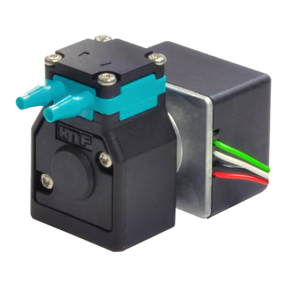
Diaphragm liquid pump NF 5, NFB 5 Assembly and function Assembly and function Assembly Outlet Inlet Connecting plate Drive Connecting leads Head plate Intermediate plate Fig. 1: diaphragm liquid pump NF 5 Outlet valve Inlet valve Working chamber Diaphragm Eccentric... -
Page 10: Installation And Connection
Diaphragm liquid pump NF 5, NFB 5 Installation and connection Installation and connection Only install the pumps under the operating parameters and condi- tions described in Chapter 4,Technical data. Observe the safety precautions (see Chapter 3). 6.1. Installation Before installation, store the pump at the installation location to bring it up to ambient temperature. - Page 11 Diaphragm liquid pump NF 5, NFB 5 Installation and connection Fig. 6: Mounting dimensions NF 5 DCB-4 Fig. 7: Mounting dimensions NFB 5 DCB Fig. 8: Mounting dimensions NFB 5 DCB-4 Installation location Make sure that the installation location is dry and the pump is protected against water in the form of rain, spray, splashes and drips.
- Page 12 Diaphragm liquid pump NF 5, NFB 5 Installation and connection Generally speaking, the pump can be installed in any position. Installation position For maximum accuracy and rapid venting of one-headed pumps, please install as shown in the illustration (Fig. ).
- Page 13 Diaphragm liquid pump NF 5, NFB 5 Installation and connection 6.2. Electrical connection Only have the pump connected by an authorized specialist. Only have the pump connected when the power supply is dis- connected. When connecting the device to a power source, the relevant norms, directives, regulations and technical standards must be observed.
- Page 14 Keep hoses between pump and junction as short as possible. Cause as little narrowing as possible with connection ele- ments. Recommendation: Min. inside diameter 1.5mm. Please contact your local KNF partner for further information Please contact your local KNF partner for further information (www.knf.com).
-
Page 15: Operation
Diaphragm liquid pump NF 5, NFB 5 Operation Operation Operate the pumps only under the operating parameters and conditions described in Chapter 4,Technical data. Make sure that the pumps are being used properly (see Chap- ter 2.1). Avoid improper use of the pumps (see Chapter 2.2). - Page 16 In order to ensure that the pump starts every time, make sure that counterpressure is reduced to an acceptable level before start-up. This should also be done during operation after a brief power cut. Please contact your local KNF partner for further in- formation (www.knf.com). Switching off the pump ...
- Page 17 Flow rate NF 5 Fig. 13: Flow rate of pump NF 5 DC-M Fig. 14: Flow rate of pump NF 5 DCB and NF 5 DCB-4 Fig. 15: Flow rate of pump NF 5 DCB-4 depending on control voltage KNF Flodos AG BA_NF5_NFB5_EN_01_172971.docx...
- Page 18 Diaphragm liquid pump NF 5, NFB 5 Operation Flow rate NFB 5 Fig. 16: Flow rate of pump NFB 5 DCB and NFB 5 DCB-4 (per pump head) Fig. 17: Flow rate of pump NFB 5 DCB-4 (per pump head) depending on control voltage KNF Flodos AG BA_NF5_NFB5_EN_01_172971.docx...
-
Page 19: Servicing
With NFB pumps, make sure that both pump heads are flushed. With NFB pumps the necessary steps are repeated for the sec- Please contact your local KNF partner for further information ond pump head. (www.knf.com). 8.2.1. Flushing the pump ... - Page 20 Diaphragm liquid pump NF 5, NFB 5 Servicing 8.2.3. Disassembling the pump head Loosen the four head screws (1) and remove the entire head. Remove both anchor valves (4) from the intermediate plate (6) and the connecting plate (3). Remove the two anchor valve seals (5) from the intermediate plate (6).
-
Page 21: Troubleshooting
Diaphragm liquid pump NF 5, NFB 5 Troubleshooting Troubleshooting Disconnect the pump from the power supply before working on the pump. Make sure that the pump is de-energised. Pump does not work Possible cause Remedy Pump not connected to power ... - Page 22 Fault cannot be rectified If you are unable to identify any of the above causes, please send the pump to KNF customer service (see address on first page). Flush the pump to clear the pump head of any hazardous or aggressive liquids (see Chapter 8.2.1).
-
Page 23: Accessories
FS 25 X PEEK 35 µm 250 ml/ min 165213 ID 3.2 / 4 mm Tab. 18 Please contact your local KNF partner for further information (www.knf.com). KNF Flodos AG BA_NF5_NFB5_EN_01_172971.docx Translated from the Original Operating and Installation Instructions... -
Page 24: Decontamination Declaration
Diaphragm liquid pump NF 5, NFB 5 Decontamination declaration 11. Decontamination declaration KNF shall only undertake to repair the pump on condition that the customer provides certification of the transferred media and the cleaning of the pump (decontamination declaration). In order to send a product back use the decontamination dec- laration, which either was delivered with the product or is avail- able on www.knf.com (Downloads). - Page 25 Diaphragm liquid pump NF 5, NFB 5 For your notes KNF Flodos AG BA_NF5_NFB5_EN_01_172971.docx Translated from the Original Operating and Installation Instructions...
- Page 26 Diaphragm liquid pump NF 5, NFB 5 For your notes KNF Flodos AG BA_NF5_NFB5_EN_01_172971.docx Translated from the Original Operating and Installation Instructions...
- Page 27 Diaphragm liquid pump NF 5, NFB 5 For your notes KNF Flodos AG BA_NF5_NFB5_EN_01_172971.docx Translated from the Original Operating and Installation Instructions...
- Page 28 KNF worldwide Please find your local KNF partners at: www.knf.com...
Need help?
Do you have a question about the NF 5 and is the answer not in the manual?
Questions and answers