Table of Contents
Advertisement
Quick Links
Advertisement
Table of Contents

Subscribe to Our Youtube Channel
Related Manuals for KNF N922FT


Summary of Contents for KNF N922FT
- Page 1 KNF 345560-345563 10/23 N922FTE TRANSLATION OF ORIGINAL OPERATING AND INSTALLATION INSTRUCTION ENGLISH DIAPHRAGM PUMP Notice! Before operating the pump and accessories, read and observe the operat- ing and installation instructions as well as the safety information!
-
Page 2: Table Of Contents
Table of contents 1 About this document ................ 3 1.1 Using the operating and installation instructions...... 3 1.2 Exclusion of liability............... 3 1.3 Symbols and markings.............. 4 2 Safety .................... 6 2.1 Personnel and target group ............ 6 2.2 Responsibility of the operator ............ 7 2.3 Working in a safety conscious manner ......... -
Page 3: About This Document
1.2 Exclusion of liability The manufacturer assumes no liability for damages and mal- functions resulting from failure to observe the operating and installation instructions. Translation of Original Operating and Installation Instruction, KNF 345560-345563 10/23... -
Page 4: Symbols And Markings
CAUTION warns of a possibly Minor injury or dangerous situation damage is possi- ble. NOTICE Warns of possible Damage is possi- damage ble. Tab.1: Danger levels Translation of Original Operating and Installation Instruction, KNF 345560-345563 10/23... - Page 5 General warning symbol Warning of hot surface Warning of electrical voltage Warning of poisonous substances Warning of hand injuries through crushing Observe the operating instructions General mandatory sign Tab.2: Explanation of pictograms Translation of Original Operating and Installation Instruction, KNF 345560-345563 10/23...
-
Page 6: Safety
Tab.3: Target group Who-does-what Lifecycle phase User Specialized per- matrix sonnel Transport Mounting Connection Commissioning Operation Servicing Troubleshooting Disposal Tab.4: Who-does-what matrix Translation of Original Operating and Installation Instruction, KNF 345560-345563 10/23... -
Page 7: Responsibility Of The Operator
Make sure that an EMC-compliant installation of the pump is ensured at all times to prevent the occurrence of dangerous situations. Translation of Original Operating and Installation Instruction, KNF 345560-345563 10/23... -
Page 8: Operating Conditions
Make sure that a dangerous situation cannot arise as a result. When pumping hazardous media, observe the safety regula- tions for the handling of said media. Translation of Original Operating and Installation Instruction, KNF 345560-345563 10/23... -
Page 9: Use
2.6.2 Foreseeable misuse The pumps must not be operated in explosive atmospheres. The pumps are not suitable for transferring the following: § Dusts § Liquids § Aerosols § Biological and microbiological substances Translation of Original Operating and Installation Instruction, KNF 345560-345563 10/23... -
Page 10: Directives And Standards
1.5.2. / 1.5.8. / 1.5.9. / 1.7.4. / 1.7.4.1. / 1.7.4.3. Standards The following standards apply: § EN 60034-1 § EN IEC 63000 The protective goals of the following directive(s) are achieved: Translation of Original Operating and Installation Instruction, KNF 345560-345563 10/23... -
Page 11: Customer Service And Repair
Alternatively, KNF products (old devices) may also be returned to KNF for a fee (see chapter 11 Re- turns [} 50]). Translation of Original Operating and Installation Instruction, KNF 345560-345563... -
Page 12: Technical Data
Flow rate at max. 6.5 ± 8 ± 10% permissible oper- ating pressure [l/ min]* Tab.6: *Liters in the standard state based on ISO 8778 and ISO 21360-1/2 (1013 mbar) Translation of Original Operating and Installation Instruction, KNF 345560-345563 10/23... - Page 13 Tab.8: Electrical parameters N922FTE 8l *For further voltage and frequency variants, see pump type plate Pneumatic connections Pump type Value N922FTE EU: Thread size G1/4* US: Thread size NPT1/4* Tab.9: *Acc. to ISO 228 Translation of Original Operating and Installation Instruction, KNF 345560-345563 10/23...
- Page 14 A leak test can be used to determine whether the original gas tightness has been re-established. Weight Parameter Value Weight [kg] Thermal switch The motors are equipped standard with a thermal switch for monitoring against overheating. Translation of Original Operating and Installation Instruction, KNF 345560-345563 10/23...
-
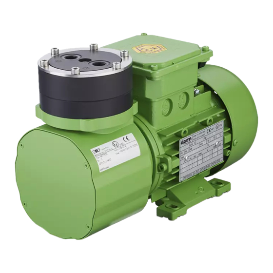
Page 15: Product Description
1 Pneumatic pump outlet 2 Pneumatic pump inlet 3 Pump head 4 Motor 5 Capacitor 6 Terminal box 7 Adjustment screw for flow rate (only .29 versions) Fig.1: Design N922FTE Translation of Original Operating and Installation Instruction, KNF 345560-345563 10/23... - Page 16 (2). In the upwards stroke, the diaphragm presses the medium out of the pump head via the outlet valve (1). The transfer chamber (3) is separated from the pump drive by the di- aphragm. Translation of Original Operating and Installation Instruction, KNF 345560-345563 10/23...
-
Page 17: Transport
à Keep the original packaging of the pump (e.g. for later storage). à Inspect the pump for transport damage after receiving it. à Document any transport damage that has occurred. Translation of Original Operating and Installation Instruction, KNF 345560-345563 10/23... - Page 18 Permissible humidity (non- 30 to 85 condensing) [%] Tab.11: Transport parameters and storage parameters Prior to commissioning, make sure that the pump has reached the ambient temperature (3 Technical data [} 12]). NOTICE Translation of Original Operating and Installation Instruction, KNF 345560-345563 10/23...
-
Page 19: Installation And Connection
Store the pump at the installation location to allow it to adapt to the ambient temperature before installation (con- densation must not be allowed to form). à Mounting dimen- For mounting dimensions, see the following illustrations: sions Translation of Original Operating and Installation Instruction, KNF 345560-345563 10/23... - Page 20 Installation and connection Diaphragm pump N922FTE Fig.3: Mounting dimensions N922FTE Translation of Original Operating and Installation Instruction, KNF 345560-345563 10/23...
- Page 21 (head, motor). à Installation loca- Make sure that the installation location is dry and that the tion pump is protected from rain, spray water, splash water, dripping water and other contaminants. Translation of Original Operating and Installation Instruction, KNF 345560-345563 10/23...
- Page 22 Risk of pump damage during operation à Take protective measures against the penetration of foreign bodies CAUTION into the pump. Translation of Original Operating and Installation Instruction, KNF 345560-345563 10/23...
-
Page 23: Aligning The Compressor Housing
2 Allen screws 3 Eccentric 4 Motor fasten- ing screws Fig.5: Remove the housing cover (illustrated pump N922FT.29E) 1. Loosen the four Allen screws (2) of the housing cover (1) and remove them. 2. Remove the housing cover (2). The eccentric, crank, motor (3) and the four motor fasten- ing screws (4) become visible. - Page 24 5. Screw the four motor fastening screws (4) back in and tighten them (tightening torque: 6 Nm). 6. Position the housing cover (1) and screw down with the four Allen screws (2) (tightening torque: 15 Ncm). Translation of Original Operating and Installation Instruction, KNF 345560-345563 10/23...
-
Page 25: Electrical Connection
à no tensile and pressure forces are exerted on the con- nection point of the cables (strain relief) The motors are protected against overload by a thermal switch as standard. Translation of Original Operating and Installation Instruction, KNF 345560-345563 10/23... - Page 26 6.1 Installing the pump [} 19] and the motor operating instructions). NOTICE 4. Connect the electrical power cables to terminals L1 and N of the pump motor. Fig.7: Electrical connection 5. Close the terminal box cover again. Translation of Original Operating and Installation Instruction, KNF 345560-345563 10/23...
-
Page 27: Pneumatic Connection
In this way it is possible to prevent the transfer of possible pump vibrations and noises to the sys- tem. Translation of Original Operating and Installation Instruction, KNF 345560-345563 10/23... - Page 28 3. Lay the suction line and pressure line with a descent so that no condensate can run into the pump. Pneumatic noises can be reduced or dissipated by using a silencer. Translation of Original Operating and Installation Instruction, KNF 345560-345563 10/23...
-
Page 29: Operation
Do not look into the pump inlet/ outlet during operation. à Only operate the pumps under the operating parameters and operating conditions as described in Chapter 3 Tech- nical data [} 12]. Translation of Original Operating and Installation Instruction, KNF 345560-345563 10/23... - Page 30 à Ensure that the pump outlet is not closed or restricted. Translation of Original Operating and Installation Instruction, KNF 345560-345563 10/23...
- Page 31 à Ensure that no dangerous situa- tions can arise as a result. Operation with open gas connection at the inlet can result in contaminants and objects being drawn in. NOTICE Translation of Original Operating and Installation Instruction, KNF 345560-345563 10/23...
-
Page 32: Information On Switching The Pump On And Off
Inspecting the Inspect the pump periodically for external damage or leak- pump age. 7.3 Adjusting the flow rate (.29 version) Tool Quantity Tool/material Screwdriver blade width 6.5 mm Tab.13: Tool/material Translation of Original Operating and Installation Instruction, KNF 345560-345563 10/23... - Page 33 When the valve is closed as well as when completely open (adjustment screw), significant resistance is felt; then turn no further. The corresponding end position is reached. X Self-locking ad- justment screw Fig.8: Adjusting the flow rate (N922FT.29E) Translation of Original Operating and Installation Instruction, KNF 345560-345563 10/23...
-
Page 34: Servicing
Servicing may only be performed according to the legal regulations (e.g. work safety, environmental protection) and provisions. à Servicing may only be performed by specialized personnel or trained and instructed personnel. Translation of Original Operating and Installation Instruction, KNF 345560-345563 10/23... -
Page 35: Servicing Schedule
8.2.1 Flushing the pump When transferring dangerous and environmentally hazardous media, KNF recommends flushing the pump with air at atmo- spheric pressure for a few minutes prior to switch-off (if nec- essary for safety reasons: with an inert gas) to extend the ser- vice life of the diaphragm. - Page 36 à Only use solvents during cleaning if head materials are not corroded (ensure resistance of the material). à If compressed air is available, blow out the components. Translation of Original Operating and Installation Instruction, KNF 345560-345563 10/23...
-
Page 37: Replacing The Diaphragm And Valve Plates/Seals (Ft Design)
Some pump parts may be hot during or after operation of the pump. WARNING à Allow the pump to cool after opera- tion. à Take protective measures to pro- tect against touching hot parts. Translation of Original Operating and Installation Instruction, KNF 345560-345563 10/23... - Page 38 4. Hold the diaphragm (6) on the side edges and unscrew it counterclockwise. 5. Check all parts for contamination and clean them if neces- sary (see Chapter Cleaning). Translation of Original Operating and Installation Instruction, KNF 345560-345563 10/23...
- Page 39 6. Check the valve seats, intermediate plate (2), head plate (3) and, if necessary, O-ring groove for contamination and damage. Clean the parts if necessary. Contact KNF in the event of unevenness, scratches or corrosion. Order and replace the damaged parts. 7. Inserting valve plate/seal: Valve plates/seals are identical for the pressure and suc- tion side;...
- Page 40 3. Checking the pump head (pump heads) and pneumatic connections for leaks: To ensure the required gas tightness of the pump follow- ing servicing, a leak test is to be performed. Translation of Original Operating and Installation Instruction, KNF 345560-345563 10/23...
- Page 41 5 Screws 6 Diaphragm 7 Screw 8 Washer 9 Valve plate/ seal 10 O-ring (only .29 version) 11 Adjusting valve (only .29 version) 12 Locating pin Fig.9: Pump parts N922FT.29E EX Translation of Original Operating and Installation Instruction, KNF 345560-345563 10/23...
-
Page 42: Changing The Adjusting Valve (.N922Fte 29 Design)
2. The valve diaphragm (Z) must be fully screwed in but Fig.10: Adjusting must not be overtightened. valve 3. Adjust the flow rate according to Adjusting the flow rate (N922FTE .29 design). Translation of Original Operating and Installation Instruction, KNF 345560-345563 10/23... -
Page 43: Spare Parts And Accessories
Spare parts and accessories Diaphragm pump N922FTE 9 Spare parts and accessories To order spare parts and accessories, please contact your KNF sales partner or KNF Customer Service (con- tact data: see www.knf.com). 9.1 Spare parts Spare part set A spare part set consists of:... -
Page 44: Accessories
Screw-in fitting, straight AD 317086 Screw-in fitting, angled AD 10 318946 Tab.21: Fig.11: Pump with accessories (N922FTE pump illustrated with mounting kit of anti-vibration buffers and mounting bracket) Translation of Original Operating and Installation Instruction, KNF 345560-345563 10/23... - Page 45 Spare parts and accessories Diaphragm pump N922FTE Fig.12: Dimensional drawing of N922FTE with mounting kit of anti-vi- bration buffers and mounting bracket Translation of Original Operating and Installation Instruction, KNF 345560-345563 10/23...
-
Page 46: Troubleshooting
à Check and ensure that no voltage is present. à Allow the pump to cool before troubleshooting. à Check the pump (see following tables). Translation of Original Operating and Installation Instruction, KNF 345560-345563 10/23... - Page 47 The applied voltage must not exceed the value specified in Chapter 6.3 Electrical connection [} 25]. à Diaphragm and valves Replace diaphragm and valves (see Chapter 8 Ser- are worn or defective. vicing [} 34]). Tab.22: Translation of Original Operating and Installation Instruction, KNF 345560-345563 10/23...
- Page 48 Stop the pump immediately. broken à Change the diaphragm (see 8 Servicing [} 34]). à Diaphragm and valves Replace diaphragm and valves (see Chapter 8 Ser- are worn or defective. vicing [} 34]). Tab.23: Translation of Original Operating and Installation Instruction, KNF 345560-345563 10/23...
- Page 49 Tab.24: Fault cannot be rectified If you are unable to identify any of the specified causes, send the pump to KNF Customer Service (contact data: see www.knf.com). 1. Flush the pump with air for a few minutes (if necessary for...
-
Page 50: Returns
If necessary, request original packaging for a fee. Returns KNF shall undertake to repair the pump only under the condi- tion that the customer presents a certificate regarding the medium that is pumped and the cleaning of the pump. In this case too, old devices can be returned. - Page 52 KNF Neuberger GmbH Alter Weg 3 79112 Freiburg Germany Tel. +49 (0)7664/5909-0 E-mail: info.de@knf.com www.knf.com KNF worldwide You can find our local KNF partners at: www.knf.com...
Need help?
Do you have a question about the N922FT and is the answer not in the manual?
Questions and answers