Table of Contents
Advertisement
Quick Links
Bulletin HY11-5715-616/UK
Operation Manual
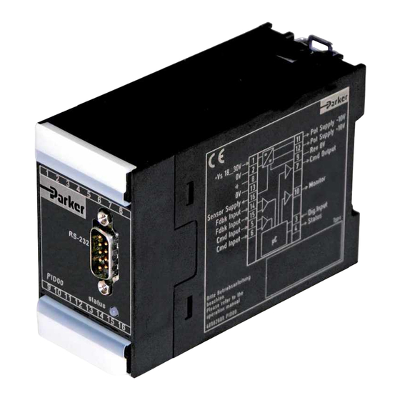
Series PID00A-40X
Design >10
Electronics for
Closed Loop Control
Parker Hannifin
Manufacturing Germany GmbH & Co. KG
Hydraulic Controls Division Europe
Gutenbergstr. 38
41564 Kaarst, Germany
Tel.: (+49) 181 99 44 43 0
E-mail: infohcd@parker.com
Copyright © 2013, Parker Hannifin Corp.
Advertisement
Table of Contents

Related Manuals for Parker PID00A-40 Series


Summary of Contents for Parker PID00A-40 Series
- Page 1 Series PID00A-40X Design >10 Electronics for Closed Loop Control Parker Hannifin Manufacturing Germany GmbH & Co. KG Hydraulic Controls Division Europe Gutenbergstr. 38 41564 Kaarst, Germany Tel.: (+49) 181 99 44 43 0 E-mail: infohcd@parker.com Copyright © 2013, Parker Hannifin Corp.
- Page 2 Parker or its subsid- iaries or authorized distributors. To the extent that Parker or its subsidiaries or authorized distributors...
-
Page 3: Table Of Contents
5.5.1. Application: Closed loop systems for position 5.5.2. Application: Closed loop systems for pressure 5.5.3. Application: Closed loop systems for velocity 5.6. Fade out function 5.7. Error messages 6. Maintenance 7. Trouble-shooting 8. Repair / Service PID00A_10 5715-616 UK.indd CM 14.11.14 Parker Hannifin Corporation Hydraulics Group... -
Page 4: Introduction
1.1. Front view / dimensions 1.2. Ordering code Electronic Universal Min/Max Technology Design module adjustment function series closed loop accel/decel ramps control command input controller Code Function Standard Linearization 1.3. Name plate PID00A_10 5715-616 UK.indd CM 14.11.14 Parker Hannifin Corporation Hydraulics Group... -
Page 5: Block Diagram
Electronics for Closed Loop Control Operation Manual Series PID00A-40X 1.4. Block diagram Parker electronic modules PID00A-40* for rail • Compatible to the relevant European EMC mounting are compact, easy to install and provide standards time-saving wiring by disconnectable terminals. •... -
Page 6: Technical Data
Screw terminals 0.2...2.5 mm², disconnectable Cable specification [AWG] 20 overall braid shield Cable length [m] 50 Options Technology function Code1 Software adjustable transfer function with 10 compensation points for linearization of valve behaviour. PID00A_10 5715-616 UK.indd CM 14.11.14 Parker Hannifin Corporation Hydraulics Group... -
Page 7: Signal Flow Diagram
Electronics for Closed Loop Control Operation Manual Series PID00A-40X 1.7. Signal flow diagram PID00A_10 5715-616 UK.indd CM 14.11.14 Parker Hannifin Corporation Hydraulics Group... -
Page 8: Safety Instructions
This operation manual is valid for module electron- ics PID00A-40X series. Any use diverging or go- ing beyond is deemed to be as not intended. The manufacturer is not liable for warranty claims re- sulting from this. PID00A_10 5715-616 UK.indd CM 14.11.14 Parker Hannifin Corporation Hydraulics Group... -
Page 9: Mounting / Installation
An additional fold- ing “unlocking lever“ allows simple removing of the terminal blocks and serves at once as shock hazard protection and marking strip. PID00A_10 5715-616 UK.indd CM 14.11.14 Parker Hannifin Corporation Hydraulics Group... -
Page 10: Electrical Interfacing
(cross section min. AWG pre-fuse of 0.5 Amp time lag. Non-observance of this instruction may create irreparable dam- 6 / 10mm²). age of electronics resp. incorporated system parts. PID00A_10 5715-616 UK.indd CM 14.11.14 Parker Hannifin Corporation Hydraulics Group... - Page 11 For the function description terminal 6 is assumed by providing a high quality in signal averting as signal reference (0V). drive malfunctions. Incorrect signal amplitude levels may disturb functionality and may damage the module! PID00A_10 5715-616 UK.indd CM 14.11.14 Parker Hannifin Corporation Hydraulics Group...
- Page 12 NAMUR is an association of users of The output will switched on when the input process control technology. signal reaches a value of 3.8mA, it switches PID00A_10 5715-616 UK.indd CM 14.11.14 Parker Hannifin Corporation Hydraulics Group...
- Page 13 The output may drive a load of max. 15mA. tions / ±20mA) Exceeding this limit leads to malfunction. • command signal cable break (only for option 4...20mA) Wiring diagram of status output PID00A_10 5715-616 UK.indd CM 14.11.14 Parker Hannifin Corporation Hydraulics Group...
- Page 14 16, the earth ground connection will be made via ter- lead to permanent damage to the electronics minal 8. The connection has to be shielded. The sen- module. sor type is selectable via software parameter E11. PID00A_10 5715-616 UK.indd CM 14.11.14 Parker Hannifin Corporation Hydraulics Group...
- Page 15 Electronics for Closed Loop Control Operation Manual Series PID00A-40X Wiring diagram of sensor input 0...±10V Wiring diagram of sensor input 0...+20mA / 4...12...20mA, 3-wire Wiring diagram of sensor input 0...+20mA / 4...12...20mA, 2-wire PID00A_10 5715-616 UK.indd CM 14.11.14 Parker Hannifin Corporation Hydraulics Group...
- Page 16 Example 1: Closed loop position control of a hydraulic cylin- der, utilizing a proportional directional control valve with integrated electronics (D*FP). Command sig- nal preset using a potentiomater. PID00A_10 5715-616 UK.indd CM 14.11.14 Parker Hannifin Corporation Hydraulics Group...
- Page 17 Series PID00A-40X Example 2: Closed loop position control of a hydraulic cylin- der, performed via proportional directional control valve with external electronic (D*FC, D*FS). Com- mand preset via external control signal. PID00A_10 5715-616 UK.indd CM 14.11.14 Parker Hannifin Corporation Hydraulics Group...
- Page 18 Example 3: Closed loop pressure control within a hydraulic cylinder, performed utilizing a proportional pres- sure con trol valve with external electronic (RE*W, VMY). Command preset via external control signal. PID00A_10 5715-616 UK.indd CM 14.11.14 Parker Hannifin Corporation Hydraulics Group...
- Page 19 Series PID00A-40X Example 4: Closed loop position control of a hydraulic cylin- der, utilizing a proportional directional control valve (D*FB) with external drive electronics PWD00. Command preset via external control signal. PID00A_10 5715-616 UK.indd CM 14.11.14 Parker Hannifin Corporation Hydraulics Group...
-
Page 20: Operating Instructions
5715543. Alternatively, the program is ted as a text file for documentation purposes or available as a download from the Parker internet down loaded to the none volatile module memory. Stored parameter sets may be loaded anytime and... -
Page 21: Program Installation
“ProPxD” program, it should Prior to the updating of older versions these has be deleted by using the Windows® - system con- to be deinstalled via the Windows® Contol Panel. trol feature. PID00A_10 5715-616 UK.indd CM 14.11.14 Parker Hannifin Corporation Hydraulics Group... -
Page 22: Software Operating
The chosen parameters may be optionally stored on the PC via the “File” menu with the menu item “Save as”, data retrieving is always pos- sible via the function “Load out of database” PID00A_10 5715-616 UK.indd CM 14.11.14 Parker Hannifin Corporation Hydraulics Group... -
Page 23: Adjustment Parameters
The “Options” menu provides also the selec- tion of the RS-232 interface port via the menu item “Port”. Via the menu item “Load out of database” previously stored parameter sets may be loaded. PID00A_10 5715-616 UK.indd CM 14.11.14 Parker Hannifin Corporation Hydraulics Group... - Page 24 4-20mA: 1 (active) 1 = ±10V 2 = ±20mA 3 = 4-20mA bipolar option command output – 1 = ±10V 12 = 4-20mA unipolar 15 = 0-10V unipolar 16 = ±50mA PID00A_10 5715-616 UK.indd CM 14.11.14 Parker Hannifin Corporation Hydraulics Group...
- Page 25 Adjustment of the operating mode for the command cable break detection. cable break detection To turn on resp. off of the cable break detection for the command signal command at a selected command signal option of 4...20mA.. PID00A_10 5715-616 UK.indd CM 14.11.14 Parker Hannifin Corporation Hydraulics Group...
- Page 26 10000 10000 0 = y=X (synchronous) set value output function – 0 = y=x 1 = y=1-x (reversal) MIN fadeout position -120.0 +120.0 -120.0 MAX fadeout position -120.0 +120.0 +120.0 PID00A_10 5715-616 UK.indd CM 14.11.14 Parker Hannifin Corporation Hydraulics Group...
- Page 27 MIN fadeout position To automate motion sequences. Adjustment of the MAX switching point for the ramped set value reduc- tion to zero. MAX fadeout position To automate motion sequences. PID00A_10 5715-616 UK.indd CM 14.11.14 Parker Hannifin Corporation Hydraulics Group...
-
Page 28: Guideline For Closed Loop Applications
D), each with a user adjustable coefficient. oscillations of the drive position. The user software provides therefore the parame- ters P16 (P), P17 (I) and P18 (D). PID00A_10 5715-616 UK.indd CM 14.11.14 Parker Hannifin Corporation Hydraulics Group... - Page 29 This should be followed by returning of the drive to the start position, where the dwell in position may also be evaluated. PID00A_10 5715-616 UK.indd CM 14.11.14 Parker Hannifin Corporation Hydraulics Group...
- Page 30 This parame- the slow oscillations. ter is only active if a window (> 0) is defined via P26. PID00A_10 5715-616 UK.indd CM 14.11.14 Parker Hannifin Corporation Hydraulics Group...
- Page 31 Please obtain detailed information from the transducer supplier. PID00A_10 5715-616 UK.indd CM 14.11.14 Parker Hannifin Corporation Hydraulics Group...
-
Page 32: Application: Closed Loop Systems For Pressure
A too low a value of P17 causes low frequency oscillations, with a too higher value the required pressure may be reached too slowly. PID00A_10 5715-616 UK.indd CM 14.11.14 Parker Hannifin Corporation Hydraulics Group... - Page 33 This should be followed by returning of the pres- sue to the start value, where the stationary value may also be evaluated. PID00A_10 5715-616 UK.indd CM 14.11.14 Parker Hannifin Corporation Hydraulics Group...
- Page 34 In this case the inte- grator operates only within this window. Select this option via parameter P26. Step increases of the window size will eliminate the oscillation. PID00A_10 5715-616 UK.indd CM 14.11.14 Parker Hannifin Corporation Hydraulics Group...
- Page 35 1000Hz. This rate is fast enough to have negligible effect in almost all hydraulic applications, but it does set an absolute limit on the response of the system. PID00A_10 5715-616 UK.indd CM 14.11.14 Parker Hannifin Corporation Hydraulics Group...
-
Page 36: Application: Closed Loop Systems For Velocity
P-gain. This term causes the output to change at a rate proportional to the error in measured pressure, in a direction to drive the steady state error to zero. PID00A_10 5715-616 UK.indd CM 14.11.14 Parker Hannifin Corporation Hydraulics Group... - Page 37 This should be followed by returning of the drive with a different velocity to evaluate also the opposite drive direction. PID00A_10 5715-616 UK.indd CM 14.11.14 Parker Hannifin Corporation Hydraulics Group...
- Page 38 You may not have any direct need for slow oscillations. fast response, but may still need a high value of P PID00A_10 5715-616 UK.indd CM 14.11.14 Parker Hannifin Corporation Hydraulics Group...
- Page 39 • Tick the “monitor output signal” box ducer, the parameters below have to be adjusted: • The button “start” activates the display of the feedback signal PID00A_10 5715-616 UK.indd CM 14.11.14 Parker Hannifin Corporation Hydraulics Group...
-
Page 40: Fade Out Function
The diagram below explains the mode of operation. The ranges may be used independently from each other. One range is inactive, if it contains the default values given from the operating software. PID00A_10 5715-616 UK.indd CM 14.11.14 Parker Hannifin Corporation Hydraulics Group... -
Page 41: Error Messages
File name.pxd already exists. Do The file name already exists within the indicated directory. Select you want to replace the file? another name, another directory or overwrite the existing file with “OK”. PID00A_10 5715-616 UK.indd CM 14.11.14 Parker Hannifin Corporation Hydraulics Group... -
Page 42: Maintenance
Reversals or disassembly may not be taken imprudently! Prior to the works it has to be clarified, if the system has been operated properly until the failure occured. PID00A_10 5715-616 UK.indd CM 14.11.14 Parker Hannifin Corporation Hydraulics Group... -
Page 43: Repair / Service
Electronics for Closed Loop Control Operation Manual Series PID00A-40X Repair / Service When you buy a Parker component, full technical support from Parker After Sales Service. Our highly qualified team will be glad to assist you in all industrial and mobile applications.
Need help?
Do you have a question about the PID00A-40 Series and is the answer not in the manual?
Questions and answers