Table of Contents
Advertisement
Quick Links
R
PORTABLE
FORCED
AIR HEATERS
OWNER'S MANUAL
Heater Sizes: 35,000 70,000 100,000 150,000 Btu/Hr
Models: B35CEA, B70CEA, B100CEA, and B150CEA
IMPORTANT
Read and understand this manual before assembling, starting or servicing
heater. Improper use of heater can cause serious injury. Keep this manual
for future reference.
Advertisement
Table of Contents

Related Manuals for Master B35CEA


Summary of Contents for Master B35CEA
- Page 1 AIR HEATERS OWNER’S MANUAL Heater Sizes: 35,000 70,000 100,000 150,000 Btu/Hr Models: B35CEA, B70CEA, B100CEA, and B150CEA IMPORTANT Read and understand this manual before assembling, starting or servicing heater. Improper use of heater can cause serious injury. Keep this manual...
-
Page 2: Table Of Contents
SECTION PAGE CONTENTS Safety Information ................2 Product Identification ................4 Unpacking ..................... 5 Assembly ....................5 Theory of Operation ................6 Fuels ..................... 6 Ventilation .................... 7 Operation ....................7 Storing, Transporting, or Shipping ............8 Preventative Maintenance Schedule ............. 8 Troubleshooting .................. - Page 3 SAFETY WARNINGS (Continued) INFORMATION • Use only kerosene or No. 1 fuel oil to avoid risk of fire or explosion. Never use gasoline, naphtha, paint thinners, alcohol, or other highly flammable fuels. Continued • Fueling a) Personnel involved with fueling shall be qualified and thoroughly familiar with the manufacturer's instructions and applicable regulations regarding the safe fu- eling of heating units.
-
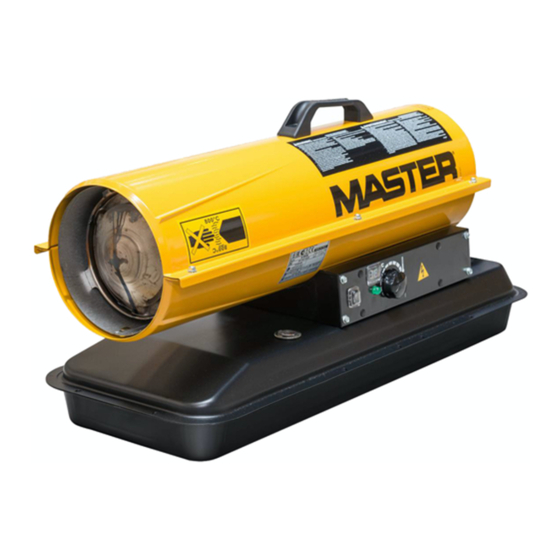
Page 4: Product Identification
PRODUCT Hot Air Outlet Handle IDENTIFICATION Upper Shell Fan Guard Lower Shell Air Filter End Cover Fuel Tank Fuel Cap Side Cover Flame-Out Control Reset Button Power Cord Figure 1 - 35/70,000 Btu/Hr Models Hot Air Outlet Upper Shell Lower Shell Fuel Cap Fan Guard... -
Page 5: Unpacking
UNPACKING 1. Remove all packing items applied to heater for shipment. 2. Remove all items from carton. 3. Check items for any shipping damage. If heater is damaged, promptly inform dealer where you bought heater. ASSEMBLY These models are furnished with wheels and handles. Wheels, handles, and the mounting hardware are found in the shipping carton. -
Page 6: Theory Of Operation
THEORY OF The Fuel System: The air pump forces air through the air line. The air is then pushed through the burner head nozzle. This air causes fuel to lift from the tank. OPERATION A fine mist of fuel is sprayed into the combustion chamber. The Air System: The motor turns the fan. -
Page 7: Ventilation
VENTILATION WARNING Follow the minimum fresh, outside air ventilation requirements. If proper fresh, outside air ventilation is not provided, carbon monoxide poisoning can occur. Provide proper fresh, outside air ventilation before running heater. Provide a fresh air opening of at least 2800 square cm (three square feet) for each 100,000 Btu/Hr rating. -
Page 8: Storing, Transporting, Or Shipping
To Stop Heater OPERATION 1. Unplug power cord from outlet. Continued To Restart Heater 1. Wait 2 minutes after stopping heater. 2. Repeat steps under To Start Heater, page 7. STORING, Note: If shipping, transport companies require fuel tanks to be empty. 1. -
Page 9: Troubleshooting
TROUBLE- WARNING SHOOTING Never service heater while it is plugged in, operating, or hot. Severe burns and electrical shock can occur. OBSERVED FAULT POSSIBLE CAUSE REMEDY Heater ignites, but Wrong pump pressure See Pump Pressure flame-out control Adjustment, page 14. shuts off heater after Dirty air output, air intake, See Air Output, Air Intake... -
Page 10: Service Procedures
SERVICE WARNING PROCEDURES Never service heater while it is plugged in, operating, or hot. Severe burns and electrical shock can occur. Upper Upper Shell Removal Shell 1. Remove screws and lock washers along each side of heater using 5/16" nut- Fan Guard driver. -
Page 11: Fuel Filter (35/70,000 Btu/Hr Models)
Fuel Filter Fuel Filter (35/70,000 Btu/Hr Models) 1. Remove side cover screws using 5/16" nut-driver. 2. Remove side cover. 3. Pull rubber fuel line off fuel filter neck. 4. Carefully pry bushing and fuel filter out of fuel tank. 5. Wash fuel filter with clean fuel and replace in tank. -
Page 12: Spark Plug (35,000 Btu/Hr Model)
Spark Plug Combustion (35,000 Btu/Hr Model) Chamber 1. Remove upper shell (see page 10). 2. Remove fan (see page 18). 3. Remove fuel and air line Spark Plug Burner hoses from nozzle Mounting Nut Strap Spark assembly. Spark Plug Plug 4. -
Page 13: Spark Plug (70/100/150,000 Btu/Hr Models)
Spark Plug (70/100/150,000 Btu/Hr Models) Spark Plug Burner 1. Remove upper shell (see Wire Head page 10). 2. Remove fan (see page 18). 3. Remove spark plug wire from spark plug. 4. Remove spark plug from burner head using 13/16" open-end wrench. -
Page 14: Air Output, Air Intake, And Lint Filters
Air Intake Filter Air Output, Air Intake, Filter End and Lint Filters Cover Fan Guard 1. Remove upper shell (see page 10). 2. Remove filter end cover screws using 5/16" nut- driver. Lint Filter 3. Remove filter end cover. Air Output 4. -
Page 15: Nozzle (35,000 Btu/Hr Model)
Nozzle Combustion Chamber (35,000 Btu/Hr Model) 1. Remove upper shell (see page 10). 2. Remove fan (see page 18). 3. Remove fuel and air line hoses from nozzle assem- bly. Nozzle 4. Turn nozzle assembly 1/4 Assembly turn to left and pull toward motor to remove. -
Page 16: Nozzle (70/100/150,000 Btu/Hr Models)
Nozzle (70/100/150,000 Btu/Hr Models) Combustion 1. Remove upper shell (see Chamber page 10). 2. Remove fan (see page 18). 3. Remove fuel and air line Spark Plug hoses from burner head. Burner Head Wire 4. Remove spark plug wire from spark plug. 5. -
Page 17: Pump Rotor
Blade Pump Rotor Pump Intake (Procedure if rotor is binding) Plate Filter 1. Remove upper shell (see Filter End page 10). Cover 2. Remove filter end cover Fan Guard screws using 5/16" nut- driver. 3. Remove filter end cover Insert and air filters. -
Page 18: Fan
IMPORTANT: Remove fan from motor shaft before removing motor from heater. The weight of the motor Setscrew resting on the fan could damage the fan pitch. 1. Remove upper shell (see page 10). 2. Use 1/8" allen wrench to loosen setscrew which holds fan to motor shaft. -
Page 19: Wiring Diagrams
230V/50Hz WIRING Blue Brown DIAGRAMS RFI Filter Black Black Green/Yellow White White Spark Plug Flame- Blue White Blue Orange Terminal Reset Ignitor Motor Board Button Control Photocell Green/ Yellow Figure 31 - Wiring Diagram, 35/100/150,000 Btu/Hr Models 230V/50Hz Blue Brown RFI Filter Black Black... -
Page 20: Illustrated Parts Breakdown And Parts List
ILLUSTRATED PARTS BREAKDOWN 35,000 Btu/Hr Model 11-5 11-1 11-2 11-4 11-3 18-1 18-2 18-18 18-4 14 10 18-5 18-6 18-7 18-3 18-8 18-17 18-16 18-9 18-15 18-10 18-11 18-14 18-12 Motor and Pump Assembly 18-13 102685... - Page 21 PARTS LIST This list contains replaceable parts used in your heater. When ordering parts, be sure to provide the correct model and serial numbers (from the model plate), then the part 35,000 Btu/Hr Model number and description of the desired part. PART PART PART...
-
Page 22: 70,000 Btu/Hr Model
ILLUSTRATED PARTS BREAKDOWN 70,000 Btu/Hr Model Burner Head Assembly 10-1 10-2 10-4 10-5 10-3 10-7 10-6 18-1 18-2 18-18 18-4 18-5 18-6 18-7 18-3 18-8 18-17 18-16 18-9 18-15 18-10 18-11 18-14 18-12 Motor and Pump Assembly 18-13 102685... - Page 23 PARTS LIST This list contains replaceable parts used in your heater. When ordering parts, be sure to provide the correct model and serial numbers (from the model plate), then the part 70,000 Btu/Hr Model number and description of the desired part. PART PART PART...
-
Page 24: 100,000 Btu/Hr Model
ILLUSTRATED PARTS BREAKDOWN 100,000 Btu/Hr Model Burner Head Assembly 13-1 13-3 13-2 13-4 13-5 13-6 13-7 13-18 13-8 13-17 13-16 13-9 13-10 13-15 13-14 13-11 13-13 Motor and Pump Assembly 13-12 102685... - Page 25 PARTS LIST This list contains replaceable parts used in your heater. When ordering parts, be sure to provide the correct model and serial numbers (from the model plate), then the part 100,000 Btu/Hr Model number and description of the desired part. PART PART PART...
-
Page 26: 150,000 Btu/Hr Model
ILLUSTRATED PARTS BREAKDOWN 150,000 Btu/Hr Model Burner Head Assembly 13-1 13-3 13-2 13-4 13-5 13-6 13-7 13-18 13-8 13-17 13-16 13-9 13-10 13-15 13-14 13-11 13-13 Motor and Pump Assembly 13-12 102685... - Page 27 PARTS LIST This list contains replaceable parts used in your heater. When ordering parts, be sure to provide the correct model and serial numbers (from the model plate), then the part 150,000 Btu/Hr Model number and description of the desired part. PART PART PART...
-
Page 28: Wheels And Handles (100/150,000 Btu/Hr Models)
WHEELS AND KEY PART PART 100,000 150,000 NO. NUMBER DESCRIPTION QTY. QTY. HANDLES HA2203 Handles — 100,000 AND 150,000 HA2204 Handles — Btu/Hr MODELS M12345-33 Screw, #10-24 x 1 3/4" M12342-3 Wheel Support Frame — M12831-3 Wheel Support Frame — NTC-3C Hex Nut, #10-24 097896-03... -
Page 29: Accessories
ACCESSORIES Purchase accessories from your local dealer. AIR GAUGE KIT - HA1180 For all models. Special tool to check pump pressure. HEAVY DUTY WHEELS AND HANDLE KIT - HA1202 For heavy duty applications. Makes your heater even more portable and convenient. For 35/70,000 Btu/Hr models. -
Page 30: Ec Conformity Declaration
Bowling Green, KY 42101 U.S.A. Kerosene Portable Forced Air Heaters Model Numbers: B35CEA, B70CEA, B100CEA, B150CEA It is declared that these models conform to the Machinery Directive 89/392/EEC, including 91/368/EEC. It is further declared that these models conform to the EMC Directive 89/336/EEC, amended by 92/31/EEC and including EN50081-1 and EN50082-1. - Page 31 NOTES 102685...
-
Page 32: Warranty And Repair Service
WARRANTY AND REPAIR SERVICE CERTIFICATE OF GENERAL EQUIPMENT - LIMITED 90 DAY WARRANTY DESA International warrants new Products sold by it to be POSE. IN ANY EVENT IMPLIED WARRANTIES INCLUDING free from defects in material or workmanship for a period of THOSE OF MERCHANTABILITY AND FITNESS FOR A PAR- ninety days after date of delivery to the first user and subject to TICULAR PURPOSE ARE LIMITED TO THE DURATION OF...
Need help?
Do you have a question about the B35CEA and is the answer not in the manual?
Questions and answers