Sign In
Upload
Download
Table of Contents
Contents
Add to my manuals
Delete from my manuals
Share
URL of this page:
HTML Link:
Bookmark this page
Add
Manual will be automatically added to "My Manuals"
Print this page
×
Bookmark added
×
Added to my manuals
Manuals
Brands
Master Manuals
Heater
B30
Owner's manual
Master B30 Owner's Manual
Portable forced air heaters
Hide thumbs
Also See for B30
:
Owner's manual
(32 pages)
1
Table Of Contents
2
3
4
5
6
7
8
9
10
11
12
13
14
15
16
17
18
19
20
page
of
20
Go
/
20
Contents
Table of Contents
Troubleshooting
Bookmarks
Table of Contents
Table of Contents
Safety Information
Product Identification
Unpacking
Assembly
Theory of Operation
Fuels
To Start Heater
Ventilation
Operation
To Stop Heater
To Restart Heater
Storage
Preventative Maintenance Schedule
Troubleshooting
Service Procedures
Upper Shell Removal
Fuel Filter (30/70,000 Btu/Hr Models)
Fuel Filter (90,000 Btu/Hr Model)
Fuel Filter (150,000 Btu/Hr Model)
Spark Plug (30,000 Btu/Hr Model)
Spark Plug (70/90/150,000 Btu/Hr Models)
Air Output, Air Intake, and Lint Filters
Pump Pressure Adjustment
Nozzle (30,000 Btu/Hr Model)
Nozzle (70/90,000 Btu/Hr Models)
Nozzle (150,000 Btu/Hr Model)
Pump Rotor
Fan
Specifications
Specifications
Wiring Diagrams
Accessories
Warranty and Repair Service
Advertisement
Quick Links
1
Fuels
2
To Start Heater
3
Troubleshooting
4
Pump Pressure Adjustment
5
Wiring Diagrams
Download this manual
R
PORTABLE
G 011
FORCED
AIR HEATERS
OWNER'S MANUAL
100 SIDE
PV 002
150 SIDE
PV 004
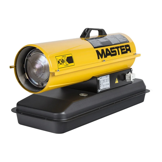
Models: B30, B70, B100, B150
IMPORTANT
Read and understand this manual before assembling, starting or servicing
heater. Improper use of heater can cause serious injury. Keep this manual
for future reference.
Table of
Contents
Previous
Page
Next
Page
1
2
3
4
5
Advertisement
Table of Contents
Need help?
Do you have a question about the B30 and is the answer not in the manual?
Ask a question
Questions and answers
Related Manuals for Master B30
Heater Master B100 Owner's Manual
Portable forced air heater (32 pages)
Heater Master B350CE Owner's Manual
High pressure portable forced air heater (24 pages)
Heater Master B 65 CEL Owner's Manual
Portable forced air heaters (15 pages)
Heater Master B 35CEL User And Maintenance Book
(18 pages)
Heater Master B35CED Owner's Manual
Portable forced air heaters heater sizes: 35,000 70,000 100,000 150,000 btu/hr (25 pages)
Heater Master B 35 CED Owner's Manual
Portable forced air heaters (21 pages)
Heater Master B35CED Owner's Manual
Portable forced air heaters (21 pages)
Heater Master BV 80 Owner's Manual
Portable forced air heaters (184 pages)
Heater Master B 3,3 ECA Owner's Manual
(37 pages)
Heater Master B 130 User And Maintenance Book
(21 pages)
Heater Master B 230 User And Maintenance Book
(39 pages)
Heater Master B 2 EPB Instructions Manual
(37 pages)
Heater Master B 2 EPB User And Maintenance Book
(13 pages)
Heater Master B 2 EPB User And Maintenance Book
(18 pages)
Heater Master B35CEA Owner's Manual
Portable forced air heaters (32 pages)
Heater Master B 3 ECA Owner's Manual
Electric air heater (37 pages)
This manual is also suitable for:
B70
B100
B150
Table of Contents
Print
Rename the bookmark
Delete bookmark?
Delete from my manuals?
Login
Sign In
OR
Sign in with Facebook
Sign in with Google
Upload manual
Upload from disk
Upload from URL


Need help?
Do you have a question about the B30 and is the answer not in the manual?
Questions and answers