Table of Contents
Advertisement
Quick Links
BI94GS-IAB Setup Manual
FCC Information and Copyright
This equipment has been tested and found to comply with the limits of a Class
B digital device, pursuant to Part 15 of the FCC Rules. These limits are designed
to provide reasonable protection against harmful interference in a residential
installation. This equipment generates, uses, and can radiate radio frequency
energy and, if not installed and used in accordance with the instructions, may
cause harmful interference to radio communications. There is no guarantee
that interference will not occur in a particular installation.
The vendor makes no representations or warranties with respect to the
contents here and specially disclaims any implied warranties of merchantability
or fitness for any purpose. Further the vendor reserves the right to revise this
publication and to make changes to the contents here without obligation to
notify any party beforehand.
Duplication of this publication, in part or in whole, is not allowed without first
obtaining the vendor's approval in writing.
The content of this user's manual is subject to be changed without notice and
we will not be responsible for any mistakes found in this user's manual. All the
brand and product names are trademarks of their respective companies.
Advertisement
Table of Contents

Related Manuals for Biostar BI94GS-IAB


Summary of Contents for Biostar BI94GS-IAB
- Page 1 BI94GS-IAB Setup Manual FCC Information and Copyright This equipment has been tested and found to comply with the limits of a Class B digital device, pursuant to Part 15 of the FCC Rules. These limits are designed to provide reasonable protection against harmful interference in a residential installation.
-
Page 2: Table Of Contents
Table of Contents Chapter 1: Introduction ........3 Before You Start ................3 Package Checklist ................3 Mainboard Specification..............4 Rear Panel..................5 Mainboard Layout ................6 Chapter 2: Installation .......... 7 CPU...................... 7 Fan Header..................7 System Memory.................. 8 Power Supply .................. -
Page 3: Chapter 1: Introduction
BI94GS-IAB CHAPTER 1: INTRODUCTION EFORE TART Thank you for choosing our product. Before you start installing the mainboard, please make sure you follow the instructions below: Prepare a dry and stable working environment with sufficient lighting. Always disconnect the system from power outlet before operation. -
Page 4: Mainboard Specification
Mini-ITX Mainboard Manual AINBOARD PECIFICATION Specification Intel CPU On-board Intel Atom N270 @1.6GHz (Mobile) Supports up to 533 MHz Northbridge: Intel 945GSE Chipset Southbridge: ICH7M Max Shared Video Memory is 224 MB ® Graphic Intel Graphic Media Accelerator 950 Supports DVI / D-Sub 128pin type ITE IT8718F Environment Control initiat ives,... -
Page 5: Rear Panel
DVI Port LAN port USB Port Audio Jack Board Size 170 mm (W) x 170 mm (L) Mini-ITX Biostar reserves the right to add or remove Windows XP/XPE, Linux Support support for any OS with or without notice. ANEL P S/2... -
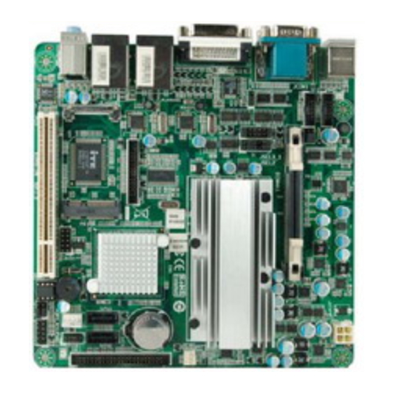
Page 6: Mainboard Layout
Mini-ITX Mainboard Manual AINBOARD AYOUT JKBMS1 JATXPWR1 COM4 JSEL 5_ 6 COM3 DIMMA1 JSEL2 Intel JSEL 4 Intel J SEL 3 _1 Atom 945GSE N270 JVG A_DVI1 CPU1 JSFAN1 IDE1 JRJ4 5 USB1 ICH7M JPRNT1 SATA1 SATA2 JRJ4 5USB2 JDIO1 JAUDIO1 JHDD1 U SB1... -
Page 7: Chapter 2: Installation
BI94GS-IAB CHAPTER 2: INSTALLATION The mainboard includes an embedded Intel Atom N270 processor, and a heatsink has been installed to provide sufficient cooling. EADER The fan header supports cooling-fans built in the system. The fan cable and connector may be different due to the fan manufacturer. -
Page 8: System Memory
Mini-ITX Mainboard Manual YSTEM EMORY DIMMA1: Memory Module (200pin SO-DIMM) Align a DIMM on the slot such that the notch on the DIMM matches the break on the Slot. Insert the DIMM firmly into the slot until the retaining chip snap back in place and the DIMM is properly seated. -
Page 9: Power Supply
BI94GS-IAB OWER UPPLY JATXPWR1: ATX Power Source Connector This connector provides +12V to system power circuit. Assignment +12V +12V Ground Ground JHDD1: SATA Power Connector This connector provides power connection of SATA devices. Assignment +12V +3.3V... -
Page 10: Onboard Slot/Connector/Header/Jumper
Mini-ITX Mainboard Manual NBOARD ONNECTOR EADER UMPER PCI1: Peripheral Component Interconnect Slot This mainboard is equipped with 1 standard PCI slot. PCI stands for Peripheral Component Interconnect, and it is a bus standard for expansion cards. This PCI slot is designated as 32 bits. PCI1 PE1: Mini PCI-E Slot This mainboard is equipped with 1 Mini PCI-E Slot. - Page 11 BI94GS-IAB IDE1: ATA Device Connector The mainboard has an integrated IDE Controller that provides PIO Mode 0~4, Bus Master, and Ultra DMA 33/66/100 functionality. It has one IDE connector which can connect a master and a slave drive, so you can connect up to two ATA devices.
- Page 12 Mini-ITX Mainboard Manual JPANEL1: Front Panel Header This 10-pin header includes Power-on, Reset, HDD LED, and Power LED connection. It allows user to connect the system case’s front panel switch functions. Assignment Function Assignment Function Power LED+ Power LED HD LED+ Power LED+ HDD LED HD LED-...
- Page 13 BI94GS-IAB JCOM1 & JCOM2: Rear Serial Port Connectors The motherboard has 2 Rear Serial Port Connectors for connecting Serial Port. COM 2 RS232 RS422 RS485 -PDCD PSIN PSOU T COM1 -PDTR -PDSR -PRTS -PCTS -PRI JSEL2: RS-232/422/485 Switch Headers for JCOM1A The header determines that JCOM1A belongs to RS-232, 422, or 485.
- Page 14 Mini-ITX Mainboard Manual JSEL3_1: Voltage Switch Header for JCOM1A (Pin1~6) JSEL3_1: RS-232/422/485 Switch Header for JCOM1A (Pin7~12) This header is for controlling the 9Pin of JCOM1A to switch 5V or 12V, and determines that JCOM1A belongs to RS-232, 422, or 485. -PRI (Default) +12V RS-232 (Default)
- Page 15 BI94GS-IAB COM3 & COM4: Serial Port Connectors The motherboard has 2 Serial Port Connectors for connecting RS-232 Port. COM4 COM3 Assignment -PDCD PSIN PSOUT data -PDTR -PDSR -PRTS -PCTS -PRI 5V / 12V JSEL5_6: Voltage Switch Header for COM3 & COM4 * This header is for controlling the 10Pin of COM3 &...
- Page 16 Mini-ITX Mainboard Manual JCMOS_AT1: Clear CMOS Header * Placing the jumper on pin1, 3, 5 allows user to restore the BIOS safe setting and the CMOS data. Please carefully follow the procedures to avoid damaging the mainboard. Pin 1-3 Close: (Default) Normal Operation.
- Page 17 BI94GS-IAB JPRNT1: Printer Port Connector This header allows you to connect printer port on the PC. Assignment Assignment -Strobe Ground -ALF Data 6 Data 0 Ground -Error Data 7 Data 1 Ground -Init -ACK Data 2 Ground -Scltin Busy Data 3...
- Page 18 Mini-ITX Mainboard Manual JDIO1: Digital I/O Connector This connector offers 4-pair of digital I/O functions and address is set in BIOS. The default address is: A21H: Output bit0~3; A22H: Input bit0~3. Assignment Digital-In-30 Digital-Out-20 Digital-In-31 Digital-Out-21 Digital-In-32 Digital-Out-22 Digital-In-33 Digital-Out-23 *How to Setup Jumpers The illustration shows how to set up jumpers.
-
Page 19: Chapter 3: Bios Setup
BI94GS-IAB CHAPTER 3: BIOS SETUP Introduction The purpose of this chapter is to describe the settings in the AMI BIOS Setup program on this motherboard. The Setup program allows users to modify the basic system configuration and save these settings to CMOS RAM. The power of CMOS RAM is supplied by a battery so that it retains the Setup information when the power is turned off. - Page 20 Mini-ITX Mainboard Manual PCI Bus Support This AMI BIOS also supports Version 2.3 of the Intel PCI (Peripheral Component Interconnect) local bus specification. DRAM Support DDR2 SDRAM (Double Data Rate II Synchronous DRAM) is supported. Supported CPUs This AMI BIOS supports the Intel CPU. Using Setup When starting up the computer, press <Del>...
-
Page 21: Main Menu
BI94GS-IAB Once you enter AMI BIOS Setup Utility, the Main Menu will appear on the screen providing an overview of the basic system information. BIOS SETUP UTILITY Main Advanced PCIPnP Boot Chipset Exit System Overview Use [ENTER], [TAB] or [SHIFT-TAB] to AMI BIOS select a field. - Page 22 Mini-ITX Mainboard Manual IDE Configuration The BIOS will automatically detect the presence of IDE/SATA devices. There is a sub-menu for each IDE/SATA device. Select a device and press <Enter> to enter the sub-menu of detailed options. BIOS SETUP UTILITY Main IDE Confuguration Options Configure SATA as...
- Page 23 BI94GS-IAB Primary IDE Master/Slave & SATA Port1/2 Devices BIOS SETUP UTILITY Main Primary IDE Master Select the type of device connected Device to the system. Type [Auto] LBA/Large Mode [Auto] Block (Multi-Sector Transfer)[Auto] PIO Mode [Auto] DMA Mode [Auto] S.M.A.R.T...
- Page 24 Mini-ITX Mainboard Manual S.M.A.R.T Set the Smart Monitoring, Analysis, and Reporting Technology. Options: Auto (Default) / Disabled / Enabled 32Bit Data Transfer Enable or disable 32-bit data transfer. Options: Enabled (Default) / Disabled Hard Disk Write Protect Disable or enable device write protection. This will be effective only if the device is accessed through BIOS.
-
Page 25: Advanced Menu
BI94GS-IAB DVANCED The Advanced Menu allows you to configure the settings of CPU, Super I/O, Power Management, and other system devices. Notice Beware of that setting inappropriate values in items of this menu may cause system to malfunction. BIOS SETUP UTILITY... - Page 26 Mini-ITX Mainboard Manual Max CPUID Value Limit When the computer is booted up, the operating system executes the CPUID instruction to identify the processor and its capabilities. Before it can do so, it must first query the processor to find out the highest input value CPUID recognizes. This determines the kind of basic information CPUID can provide the operating system.
- Page 27 BI94GS-IAB SuperIO Configuration BIOS SETUP UTILITY Advanced Configure ITE8718 Super IO Chipset PCI IRQ Sharing for OS(EX.WinXP) Second IO UART IRQ MODE [PCI IRQ Sharing] ISA IRQ Sharing for Serial Port 1-4 IRQ Share [IRQ5] Serial Port1 Address [3E8] Serial Port1 IRQ...
- Page 28 Mini-ITX Mainboard Manual Serial Port2 IRQ This item allows you to select IRQ of Serial Port2. Options: IRQ5 (Default) / IRQ3 / IRQ4 / IRQ7 / IRQ9 / IRQ10 / IRQ11 Serial Port3 Address This item allows you to select the address of Serial Port3. Options: 2F0 (Default) / 3E8 / 2E8 / 2E0 Serial Port3 IRQ This item allows you to select IRQ of Serial Port3.
- Page 29 BI94GS-IAB ECP Mode DMA Channel This item allows you to select parallel port ECP DMA. Options: DMA3 (Default) / DMA0 / DMA1 Parallel Port IRQ This item allows you to select the IRQ for the onboard parallel port. Options: IRQ7 (Default) / IRQ5 Watch Dog Degree This item allows you to determine the functional degree of Watch Dog.
- Page 30 Mini-ITX Mainboard Manual ACPI Configuration BIOS SETUP UTILITY Advanced ACPI Settings Advanced ACPI Configuration settings Power Supply Emulate Mode: > Advanced ACPI Configuration Use this section to > Chipset ACPI Configuration configure additional Resume On PME# [Disabled] ACPI options. Resume On RTC Alarm [Disabled] Restore on AC Power Loss by IO [Powre Off] Select Screen...
- Page 31 BI94GS-IAB AMI OEMB table Set this value to allow the ACPI BIOS to add a pointer to an OEMB table in the Root System Description Table (RSDT) table. Options: Enabled (Default) / Disabled Headless mode This is a server-specific feature. A headless server is one that operates without a keyboard, monitor or mouse.
- Page 32 Mini-ITX Mainboard Manual Resume On RTC Alarm When “Enabled”, you can set the date and time at which the RTC (real-time clock) alarm awakens the system from Suspend mode. Options: Disabled (Default) / Enabled RTC Alarm Date (Days) You can choose which date the system will boot up. RTC Alarm Time You can choose the system boot up time, input hour, minute and second to specify.
- Page 33 BI94GS-IAB Legacy USB Support This item determines if the BIOS should provide legacy support for USB devices like the keyboard, mouse, and USB drive. This feature is useful for using USB devices with operating systems that do not natively support USB (e.g. Microsoft MS-DOS or Windows NT).
-
Page 34: Pci/Pnp Menu
Mini-ITX Mainboard Manual PCI/P This section describes configuring the PCI bus system. PCI, or Personal Computer Interconnect, is a system which allows I/O devices to operate at speeds nearing the speed of the CPU itself uses when communicating with its own special components. Notice Beware of that setting inappropriate values in items of this menu may cause system to malfunction. - Page 35 BI94GS-IAB PCI Latency Timer This item controls how long a PCI device can hold the PCI bus before another takes over. The longer the latency, the longer the PCI device can retain control of the bus before handing it over to another PCI device.
- Page 36 Mini-ITX Mainboard Manual PCI Resource BIOS SETUP UTILITY PCIPnP PCI Resource Available: Specified IRQ is available to be IRQ3 [Available] used by PCI/PnP IRQ4 [Available] devices. IRQ5 [Available] Reserved: Specified IRQ7 [Available] IRQ is reserved for IRQ9 [Available] use by Legacy ISA IRQ10 [Available] devices.
-
Page 37: Boot Menu
BI94GS-IAB This menu allows you to setup the system boot options. BIOS SETUP UTILITY Main Advanced PCIPnP Boot Chipset Exit Boot Settings Configuration Specifies the Boot Device Priority sequence. > Boot Device Priority > Hard Disk Drives > Removable Drives >... - Page 38 Mini-ITX Mainboard Manual CD/DVD Drives The BIOS will attempt to arrange the CD/DVD drive boot sequence automatically. You can also change the booting sequence. The number of device items that appears on the screen depends on the number of devices installed in the system. Quick Boot Enabling this option will cause an abridged version of the Power On Self-Test (POST) to execute after you power up the computer.
- Page 39 BI94GS-IAB Hit ‘DEL’ Message Display This BIOS feature allows you to control the display of the Hit “DEL” to enter Setup message during memory initialization. Options: Enabled (Default) / Disabled Interrupt 19 Capture Interrupt 19 is the software interrupt that handles the boot disk function. When set to Enabled, this item allows the option ROMs to trap interrupt 19.
-
Page 40: Chipset Menu
Mini-ITX Mainboard Manual HIPSET This submenu allows you to configure the specific features of the chipset installed on your system. This chipset manage bus speeds and access to system memory resources, such as DRAM. It also coordinates communications with the PCI bus. Notice Beware of that setting inappropriate values in items of this menu may cause system to malfunction. - Page 41 BI94GS-IAB North Bridge Configuration BIOS SETUP UTILITY Chipset North Bridge Chipset Configuration Options DRAM Frequency [Auto] Auto Configure DRAM Timing by SPD [Enabled] 400 Mhz DRAM CAS# Latency 533 Mhz DRAM RAS# to CAS# Delay [6 DRAM Clocks] DRAM RAS# Precarge...
- Page 42 Mini-ITX Mainboard Manual DRAM RAS# Activate to Precharge Options: 15 DRAM Clocks (Default) / 4 ~ 14 DRAM Clocks Memory Hole You can reserve this area of system memory for ISA adapter ROM. When this area is reserved it cannot be cached. Check the user information of peripherals that need to use this area of system memory for the memory requirements.
- Page 43 BI94GS-IAB DVMT/FIXED Memory DVMT stands for “Dynamic Video Memory Technology”. This is an enhancement of the unified memory architecture (UMA) concept. DVMT will set the optimum amount of memory to be allocated for a balance between graphics and system performance. DVMT dynamically respond to system requirements and applications demands, by allocating the proper amount of display, texturing and buffer memory after the operating system has booted.
- Page 44 Mini-ITX Mainboard Manual SMBUS Controller This BIOS feature controls the I/O buffers for the SMBus. Options: Enabled (Default) / Disabled SLP_S4# Min. Assertion Width Options: 1 to 2 seconds (Default) /4 to 5 seconds / 3 to 4 seconds / 2 to 3 seconds Onboard LAN 1/2 This item allows you to enable or disable the Onboard LAN 1/2.
-
Page 45: Exit Menu
BI94GS-IAB This menu allows you to load the optimal default settings, and save or discard the changes to the BIOS items. BIOS SETUP UTILITY Main Advanced PCIPnP Boot Chipset Exit Exit Options Exit system setup after saving the Save Changes and Exit changes. - Page 46 Mini-ITX Mainboard Manual Security This sub-menu allows you to provide/revise supervisor and user password. BIOS SETUP UTILITY Exit Security Settings Install or Change the password. Supervisor Password :Not Installed User Password :Not Installed Change Supervisor Password User Access Level [Full Access] Change User Password Clear User Password Password Check...
- Page 47 BI94GS-IAB Password Check This item is for setting the timing that checking password. Options: Setup (Default) / Always Boot Sector Virus Protection This option allows you to choose the VIRUS Warning feature that is used to protect the IDE Hard Disk boot sector. If this function is enabled and an attempt is made to write to the boot sector, BIOS will display a warning message on the screen and sound an alarm beep.
-
Page 48: Chapter 4: Useful Help
Mini-ITX Mainboard Manual CHAPTER 4: USEFUL HELP RIVER NSTALLATION After you installed your operating system, please insert the Fully Setup Driver CD into your optical drive and install the driver for better system performance. You will see the following window after you insert the CD The setup guide will auto detect your mainboard and operating system. -
Page 49: Ami Bios Beep Code
BI94GS-IAB AMI BIOS B Boot Block Beep Codes Number of Beeps Description No media present. (Insert diskette in floppy drive A:) “AMIBOOT.ROM” file not found in root directory of diskette in Insert next diskette if multiple diskettes are used for recovery... -
Page 50: Troubleshooting
Mini-ITX Mainboard Manual ROUBLESHOOTING Probable Solution There is no power in the system. Make sure power cable is Power LED does not shine; the securely plugged in. fan of the power supply does not Replace cable. work Contact technical support. Indicator light on keyboard does not shine.
Need help?
Do you have a question about the BI94GS-IAB and is the answer not in the manual?
Questions and answers