Table of Contents
Advertisement
Quick Links
FCC Warning
This equipment has been tested and found to comply with the limits for a Class A digital device, pursuant
to part 15 of the FCC Rules. These limits are designed to provide reasonable protection against harmful
interference when the equipment is operated in a commercial environment. This equipment generates, uses,
and can radiate radio frequency energy and, if not installed and used in accordance with the instruction
manual, may cause harmful interference to radio communications. Operation of this equipment in a
residential area is likely to cause harmful interference in which case the user will be required to correct the
interference at his own expense.
Advertisement
Table of Contents

Related Manuals for Biostar BIH41-IHP


Summary of Contents for Biostar BIH41-IHP
-
Page 1: Fcc Warning
FCC Warning This equipment has been tested and found to comply with the limits for a Class A digital device, pursuant to part 15 of the FCC Rules. These limits are designed to provide reasonable protection against harmful interference when the equipment is operated in a commercial environment. This equipment generates, uses, and can radiate radio frequency energy and, if not installed and used in accordance with the instruction manual, may cause harmful interference to radio communications. -
Page 2: Table Of Contents
Table Of Contents FCC Warning ����������������������������������������������������������������������������������������������������������� 1 Chapter 1: Introduction ������������������������������������������������������������������������������������������� 3 1.1 Before You Start .............................3 1.2 Specifications ............................4 1.3 Rear Panel Connectors ...........................6 Chapter 2: Hardware installation ����������������������������������������������������������������������������� 9 2.1 Install Central Processing Unit (CPU) .....................9 2.2 Install a Heatsink ..........................11 2.3 Fan Headers ............................12 2.4 Installing Memory Module ........................12 2.5 Expansion Slots ............................13... -
Page 3: Chapter 1: Introduction
BIH41-IHP User’s Manual Chapter 1: Introduction 1�1 Before You Start Thank you for choosing our product. Before you start installing the motherboard, please make sure you follow the instructions below: • Prepare a dry and stable working environment with sufficient lighting. -
Page 4: Specifications
1�2 Specifications Intel® Comet Lake s for LGA1200 Socket CPU (Max TDP at 65W) Chipset Intel® H410 Intel® Integrated Graphics: eDP -- 1x eDP 40 pin connector DP -- 1x DP connector combo with dual USB3.0 connector (1x DP + 2x USB3.0), support resolution Graphic 4096*2304 @60Hz. - Page 5 BIH41-IHP User’s Manual Board Size 170 mm x 170 mm Operation Temperature 0°C ~ 60°C Storage Temperature -10ºC ~ 70ºC Relative Humidity 5% ~ 90% (non-condensing) Watchdog Timer Reset; 1 sec.~255 min. and 1 sec. or 1 min. /step Comply FCC Class B OS Driver Support Win10 (only support 64bit), Linux Ubuntu 18.04...
-
Page 6: Rear Panel Connectors
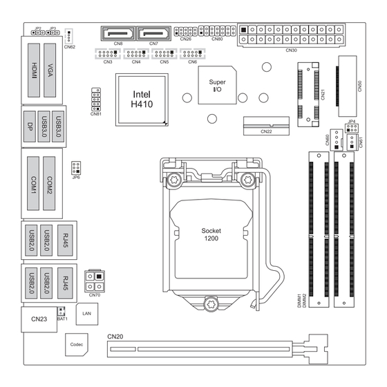
1�3 Rear Panel Connectors CN10/ CN11: COM Port (DB9) Mode RS-422 RS-485 RS-232 Pin Define (1T/1R Full (1T/1R TX Enable (3T/5R) Duplex) Low Active) COM1C_DCD TX(B) (R(B) / T(B)) COM1C_RXD TX(A) (R(A) / T(A)) COM1C_TXD RX(A) COM1C_DTR RX(B) COM1C_DSR COM1C_RTS COM1C_CTS COM1C_RI 6 | Chapter 1: Introduction... - Page 7 BIH41-IHP User’s Manual 1�4 Motherboard Layout » » represents the 1st pin. Chapter 1: Introduction | 7...
- Page 8 Back View 8 | Chapter 1: Introduction...
-
Page 9: Chapter 2: Hardware Installation
BIH41-IHP User’s Manual Chapter 2: Hardware installation 2�1 Install Central Processing Unit (CPU) Step 1: Locate the CPU socket on the motherboard Note »» Remove pin cap before installation, and make good preservation for future use. When the CPU is removed, cover the pin cap on the empty socket to ensure pin legs won’t be damaged. »» The motherboard might equip with two different types of pin cap. Please refer below instruction to remove the pin cap. Step 2: Pull the socket locking lever out from the socket and then raise the lever up. - Page 10 Step 4: Hold processor with your thumb and index fingers, oriented as shown. Align the notches with the socket. Lower the processor straight down without tilting or sliding the processor in the socket. Step 5: Hold the CPU down firmly, and then lower the lever to locked position to complete the installation. Note »» ...
-
Page 11: Install A Heatsink
BIH41-IHP User’s Manual 2�2 Install a Heatsink Step 1: Place the CPU fan assembly on top of the installed CPU and make sure that the four fasteners match the motherboard holes. Orient the assembly and make the fan cable is closest to the CPU fan connector. -
Page 12: Fan Headers
2�3 Fan Headers These fan headers support cooling-fans built in the computer. The fan cable and connector may be different according to the fan manufacturer. Connect the fan cable to the connector while matching the black wire to pin#1. CN60: CPU Fan Header Pin Assignment Ground FANPVOUT... -
Page 13: Expansion Slots
BIH41-IHP User’s Manual Insert memory module into SO-DIMM socket at backside of motherboard. Hold the SO-DIMM with its notch aligned with the memory socket of the board and insert it at a 30-degree angle into the socket. Press down on the SO-DIMM so that the tabs of the socket lock on both sides of the module. - Page 14 CN22: M�2 (E Key) Socket • Support M.2 socket 2230 type module. • Supports PCIex1 and USB2.0 . SCN1: M�2 (B Key) Socket • Supports M.2 socket 2242/ 2280/ 3042/ 3052 type module. • Supports PCIEx2, PCIe + SATA3.0, PCIe + USB3.1 interfaces by BOM option. (Default is PCIe + USB3.0.) Installing WiFi Module Insert WiFi module into mini PCIe slot (CN21)
-
Page 15: Jumper & Switch Setting
BIH41-IHP User’s Manual 2�6 Jumper & Switch Setting Jumper Setting The illustration shows how to set up jumpers. When the jumper cap is placed on pins, the jumper is “close”, if not, that means the jumper is “open”. Pin opened... -
Page 16: Headers & Connectors
JP6: COM VDD Pin 3-5 Close: 5V level (Default) Pin 4-6 Close: 12V level (Default) 2�7 Headers & Connectors CN30: ATX Power Source Connector For better compatibility, we recommend to use a standard ATX 24-pin power supply for this connector. Make sure to find the correct orientation before plugging the connector. - Page 17 BIH41-IHP User’s Manual JP2: AT-ATX Power Source Connector The connector provides +12V to the CPU power circuit. Pin 1-2 Close: ATX Mode Pin 2-3 Close: AT Mode CN80: Front Panel Header This connector includes Power-on, Reset, HDD LED and Power LED connections. It allows user to connect the PC case’s front panel switch functions.
- Page 18 CN3/ CN4/ CN5/ CN6: COM Header Assignment Assignment Ground CN62: USB Header These connectors support the thin Serial ATA cable for primary internal storage devices. Pin Assignment Power Ground CN50: EDP Connector This connector supports 18/24 bit single-channel panels. Assignment Assignment VDD[*] VDD[*]...
- Page 19 BIH41-IHP User’s Manual CN81: SPI Header Pin Assignment MISO MOSI CN26: Digital I/O Connector Pin Assignment Ground SCN2: SIM Slot Pin Assignment UIM_PWR UIM_Reset UIM_CLK Data Chapter 2: Hardware installation | 19...
Need help?
Do you have a question about the BIH41-IHP and is the answer not in the manual?
Questions and answers