Table of Contents
Advertisement
Quick Links
This equipment has been tested and found to comply with the limits of a Class B digital device, pursuant
to Part 15 of the FCC Rules. These limits are designed to provide reasonable protection against harmful
interference in a residential installation. This equipment generates, uses, and can radiate radio frequency
energy and, if not installed and used in accordance with the instructions, may cause harmful interference to
radio communications. There is no guarantee that interference will not occur in a particular installation.
The vendor makes no representations or warranties with respect to the contents here and specially disclaims
any implied warranties of merchantability or fitness for any purpose. Further the vendor reserves the right
to revise this publication and to make changes to the contents here without obligation to notify any party
beforehand.
Duplication of this publication, in part or in whole, is not allowed without first obtaining the vendor's approval
in writing.
The content of this user's manual is subject to be changed without notice and we will not be responsible for
any mistakes found in this user's manual. All the brand and product names are trademarks of their respective
companies.
FCC Information and Copyright
Dichiarazione di conformità sintetica
Ai sensi dell'art. 2 comma 3 del D.M. 275 del
30/10/2002
Si dichiara che questo prodotto è conforme
alle normative vigenti e soddisfa i requisiti
essenziali richiesti dalle direttive
2004/108/CE, 2006/95/CE e 1999/05/CE
quando ad esso applicabili
Short Declaration of conformity
We declare this product is complying with the
laws in force and meeting all the essential
requirements as specified by the directives
2004/108/CE, 2006/95/CE and 1999/05/CE
whenever these laws may be applied
Advertisement
Table of Contents

Related Manuals for Biostar BICMA-IHP


Summary of Contents for Biostar BICMA-IHP
-
Page 1: Fcc Information And Copyright
FCC Information and Copyright This equipment has been tested and found to comply with the limits of a Class B digital device, pursuant to Part 15 of the FCC Rules. These limits are designed to provide reasonable protection against harmful interference in a residential installation. -
Page 2: Table Of Contents
Table Of Contents FCC Information and Copyright ������������������������������������������������������������������������������� 1 Chapter 1: Introduction ������������������������������������������������������������������������������������������� 2 1.1 Before You Start .............................2 1.2 Specifications ............................4 1.3 Rear Panel Connectors ...........................6 1.4 Motherboard Layout ..........................7 Chapter 2: Hardware installation ����������������������������������������������������������������������������� 8 2.1 Central Processing Unit (CPU) ........................8 2.2 Connect Cooling Fan ..........................8 2.3 Installing System Memory ........................8 2.4 Power Supply ............................9... -
Page 3: Chapter 1: Introduction
BICMA-IHP User’s Manual Chapter 1: Introduction 1�1 Before You Start Thank you for choosing our product. Before you start installing the motherboard, please make sure you follow the instructions below: • Prepare a dry and stable working environment with sufficient lighting. -
Page 4: Specifications
1�2 Specifications Intel® Comet lake s for LGA1200 Socket CPU Chipset Intel® H420E Intel® Integrated Graphics 1x DP connector, support resolution 4096*2304 @60Hz. HDMI Graphic 1 x HDMI connector, resolution up to 4096 x 2160@24Hz LVDS 1). 18/24 bit dual channels co-lay eDP, (by BOM option) 2). - Page 5 BICMA-IHP User’s Manual Expansion slots 2x 260-pin socket support DDR4 2666MHz SO-DIMM 2x 1*7 pin SATA connector 1 x M.2 key M type 2242/2280 with PCIEx4 and SATA3.0 (H420E only support SATA) 1 x M.2 key E type 2230 with PCIEx1 and USB2.0...
-
Page 6: Rear Panel Connectors
1�3 Rear Panel Connectors Standard DC1: DC-12V Input Connector 6 | Chapter 1: Introduction... -
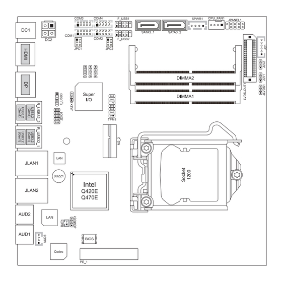
Page 7: Motherboard Layout
BICMA-IHP User’s Manual 1�4 Motherboard Layout Note » » represents the 1st pin. Chapter 1: Introduction | 7... -
Page 8: Chapter 2: Hardware Installation
Chapter 2: Hardware installation 2�1 Central Processing Unit (CPU) The mainboard includes an onboard Intel® SOC, and a cooler has been installed to provide sufficient cooling. 2�2 Connect Cooling Fan The fan header supports cooling-fans built in the computer. The fan cable and connector may be different according to the fan manufacturer. -
Page 9: Power Supply
BICMA-IHP User’s Manual Memory Capacity DIMM Socket Location DDR4 Module Total Memory Size DIMMA1 512MB/1GB/2GB/4GB/8GB/16GB/32GB Max is 64GB DIMMB1 512MB/1GB/2GB/4GB/8GB/16GB/32GB 2�4 Power Supply DC2: ATX Power Source Connector (4-pin) This connector provides or +12V input to system power circuit. Pin Assignment... -
Page 10: Jumpers / Headers / Connectors
2�5 Jumpers / Headers / Connectors Jumper Setting The illustration shows how to set up jumpers. When the jumper cap is placed on pins, the jumper is “close”, if not, that means the jumper is “open”. Pin opened Pin closed Pin 1-2 closed JCMOS1: Clear CMOS Jumper Placing the jumper on pin2-3 allows user to restore the BIOS safe setting and the CMOS data. - Page 11 BICMA-IHP User’s Manual SATA3_1/SATA3_2: Serial ATA 3.0 Gb/s Connectors These connectors support the thin Serial ATA cable for primary internal storage devices. Pin Assignment » » SATA2 is shared with Mini PCI-E slot. TPM1: Trusted Platform Module Header This header allows you to store cryptographic keys that protect information.
- Page 12 Serial Port Connectors & Headers JPC1: COM1 Serial Port Voltage Switch Jumper JPC2: COM2 Serial Port Voltage Switch Jumper COM1/COM2/COM3/COM4: Serial Port Headers Pin Assignment Assignment SOUT M1/M2/M3: COM Port Mode Selection (For COM1) Assignment 0 (Pin 2-3) 0 (Pin 2-3) 0 (Pin 1-2) RS232 (Default) 0 (Pin 2-3) 1 (Pin 1-2) 1 (Pin 2-3) RS485 0 (Pin 2-3) 0 (Pin 2-3) 0 (Pin 2-3) RS422 » ...
- Page 13 BICMA-IHP User’s Manual JC1: LCD Backlight Inverter Connector This connector is for connecting to LCD for providing backlight control function. Pin Assignment BL_POWER BL_POWER BL_EN BL_CTL Ground Ground JLV1: LCD Panel Power Select Jumper This jumper is for selecting LCD Power.
- Page 14 LVDS-OUT1: LVDS Connector This connector supports 18/24 bit single-channel panels. Pin Assignment Assignment LVDSB_DATA0_N PVDD2 LVDSB_DATA0_P PVDD2 LVDSB_DATA1_N LVDSB_DATA1_P LVDSA_DATA0_N LVDSA_DATA0_P LVDSB_DATA2_N LVDSB_DATA2_P LVDSA_DATA1_N LVDSA_DATA1_P LVDSB_CLK_N LVDSB_CLK_P LVDSA_DATA2_N LVDSA_DATA2_P LVDSB_DATA3_N LVDSB_DATA3_P LVDSA_CLK_N VCC5 LVDSA_CLK_P LVDS-EDID_SCL VCC3_3 LVDSA_DATA3_N SEL88/ HPD LVDSA_DATA3_P PVDD2 PVDD2 LVDS_EDID_SDA...
- Page 15 BICMA-IHP User’s Manual AUD3: Audio Line Out Connector Assignment JDIO1: Digital I/O Connector This connector offers 4-pair of digital I/O functions and address is set in BIOS. Pin Assignment DI01 DO01 DI02 DO02 DI03 DO03 DI04 DO04 10 GND Chapter 2: Hardware installation | 15...
-
Page 16: 2.6 Expansion Slots
2.6 Expansion Slots PE_1: PCIEx4 Slot PCI-Express 2.0 compliant. Data transfer bandwidth up to 500MB/s per direction; 1GB/s in total Install an Expansion Card You can install your expansion card by following steps: • Read the related expansion card’s instruction document before install the expansion card into the computer.
Need help?
Do you have a question about the BICMA-IHP and is the answer not in the manual?
Questions and answers