Table of Contents
Advertisement
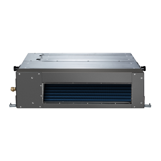
Ducted Style Ductless System − Sizes 09 to 58
Fig. 1 - Sizes 09−48
Fig. 2 - Size 58
NOTES:
Read the entire instruction manual before starting the installation.
Images are for illustration purposes only. Actual models may differ
slightly.
DLFSDA and DLFLDA
INSTALLATION INSTRUCTIONS
Specifications subject to change without notice.
TABLE OF CONTENTS
. . . . . . . . . . . . . . . . . . . . . . . . . . . . . . . . . . . . . . . . . . .
. . . . . . . . . . . . . . . . . . . . . . . . . . . . . . .
. . . . . . . . . . . . . . . . . . . . . . . . . . . . . . . . . . . . . . . . . . . . . . .
. . . . . . . . . . . . . . . . . . . . . . . . . . . . . . . . . . . . . . . . . .
. . . . . . . . . . . . . . . . . . . . . . . . . . . . . . . . . . .
. . . . . . . . . . . . . . . . . . . . . . . . . . . . . . . . . . . . . . . . . . . .
. . . . . . . . . . . . . . . . . . . . . . . . . . . . . . . . . .
. . . . . . . . . . . . . . . . . . . . . . . . . . . . .
. . . . . . . . . . . . . . . . . . . . . . . . . . .
. . . . . . . . . . . . . . . . . . . . . . . . . .
. . . . . . . . . . . . . .
. . . . . . . . . . . . . . . . . . . . . . . . . . .
. . . . . . . . . . . . . . . . . . . . . . . . .
. . . . . . . . . . . . . . . . . . . . . . . . . . . . .
PAGE
2
3
4
4
5
7
7
8
8
12
. . . .
13
21
21
24
25
Advertisement
Table of Contents

Related Manuals for Midea DLFSDA


Summary of Contents for Midea DLFSDA
-
Page 1: Table Of Contents
DLFSDA and DLFLDA INSTALLATION INSTRUCTIONS Ducted Style Ductless System − Sizes 09 to 58 TABLE OF CONTENTS PAGE SAFETY CONSIDERATIONS ...... -
Page 2: Safety Considerations
SAFETY CONSIDERATIONS Installing, starting up, and servicing air−conditioning equipment can be WARNING hazardous due to system pressures, electrical components, and equipment location (roofs, elevated structures, etc.). Only trained, qualified installers and service mechanics should install, ELECTRICAL SHOCK HAZARD start−up, and service this equipment. Failure to follow this warning could result in personal Untrained personnel can perform basic maintenance functions such as injury or death. -
Page 3: Parts List
PARTS LIST Table 1—Parts List PART NAME INDOOR UNIT DRAIN ADAPTER AIR FILTER WIRED CONTROLLER WIRELESS REMOTE LITERATURE PACKAGE INCLUDING INSTALLATION INSTRUCTIONS AND WARRANTY CONDENSATE LIFT PUMP (EXTERNAL SIZES 09-18, INTERNAL SIZES 24-58) Air inlet Electric control cabinet Air filter Drain hose(field supplied) Air outlet Refrigerant connecting pipe... -
Page 4: System Requirements
SYSTEM REQUIREMENTS Allow sufficient space for airflow and servicing unit. See Fig. 6 for minimum required distances between the unit and the walls or ceilings. Piping IMPORTANT: Both refrigerant lines must be insulated separately. S Minimum refrigerant line length between the indoor and outdoor units is 10 ft. (3 m). S Table 3 lists the pipe sizes for the indoor unit. -
Page 5: Dimensions
DIMENSIONS Air inlet from rear side Air filter 4-install hanger Test mouth & Test cover Outside air intake Electric control box 0.98in (25mm) Drain connecting pipe (for lift pump) 0.98in (25mm) Drain pipe Gas connection Liquid connection Airflow Air inlet from bottom side Air filter Airflow Fig. - Page 6 DIMENSIONS − (CONT) Airflow Airflow Fig. 5 - Indoor Unit Sizes 58K 32801000302 Specifications subject to change without notice.
-
Page 7: Installation Clearances
INSTALLATION CLEARANCES > 11.8in(30cm) Strong and durable ceiling >0.8in(2cm) Indoor unit Right Left side side > 0.8in(2cm) Access Panel Ceiling opening size Service access Ceiling > > Ceiling opening size Floor Maintenance space Fig. 6 - Installation Clearances MAINTENANCE CLEARANCES Bottom Return Blower/Motor Service Clearance Service access... -
Page 8: Installation Location Requirements
INSTALLATION LOCATION REQUIREMENTS Indoor Unit 5. Secure the unit in position with lock nuts and washers on both S Confirm that the ceiling is able to support the weight of the unit. sides of the mounting bracket. Ensure the threaded rod does not S There should be enough room within the false ceiling for installation extend more than 2 in. - Page 9 INSTALLING DUCTWORK Connect the return and supply ducts to the duct collars provided on the Condensate piping must not be installed where it may be exposed to unit. Adequate distance between the return and supply diffusers should be freezing temperatures. maintained to avoid short circulation of air within the space.
- Page 10 CONDENSATE DRAIN AND CONDENSATE LIFT (3.) Sizes 24, 36, 48 and 58 have a built−in condensate lift pump. The drain connections (A, B and C) are covered with caps. PUMP INSTALLATION (HORIZONTAL a. Connect the drainpipe to connector D (see Fig. 21). INSTALLATION) For sizes 9, 12 and 18, the condensate lift pump has been provided in a separate box.
- Page 11 Remove the cap from connector C and connect the condensate drain pipe to drain connector C. (see Fig. 25). NOTE: For size 18, the External Condensate lift pump should be removed (see Fig. 24). Connector C Fig. 24 - Sizes 9, 12, 18 with External Condensate Lift Pump Connector C Fig.
-
Page 12: External Static Pressure
EXTERNAL STATIC PRESSURE Using the KSACN0501AAA Wired Controller, the external static CAUTION CAUTION pressure can: Be manually changed to the fan curves SP2, SP3, SP4. DAMPERS Choose the Automatic Airflow “AF” adjustment function which will automatically identify the static pressure and regulate the amount of DO NOT adjust the dampers when the automatic airflow airflow. -
Page 13: Fan Performances At Varying Static Pressures
FAN PERFORMANCES AT VARYING STATIC PRESSURES Table 6—Static Pressure at the Rated Point and Static Pressure Range Static Pressure at Rated Point Size Units Static Pressure Range In. WG 0.068 0.104 0.128 0.176 0~0.20 (0~50) In. WG 0.064 0.10 0.136 0.20 0~0.20 (0~50) - Page 14 FAN PERFORMANCES AT VARYING STATIC PRESSURES (CONT) Fig. 32 - Fan Performance − 40MBDQ09 32801000302 Specifications subject to change without notice.
- Page 15 FAN PERFORMANCES AT VARYING STATIC PRESSURES (CONT) Fig. 33 - Fan Performance − 40MBDQ12 Specifications subject to change without notice. 32801000302...
- Page 16 FAN PERFORMANCES AT VARYING STATIC PRESSURES (CONT) Fig. 34 - Fan Performance − 40MBDQ18 32801000302 Specifications subject to change without notice.
- Page 17 FAN PERFORMANCES AT VARYING STATIC PRESSURES (CONT) Fig. 35 - Fan Performance − 40MBDQ24 Specifications subject to change without notice. 32801000302...
- Page 18 FAN PERFORMANCES AT VARYING STATIC PRESSURES (CONT) Fig. 36 - Fan Performance − 40MBDQ36 32801000302 Specifications subject to change without notice.
- Page 19 FAN PERFORMANCES AT VARYING STATIC PRESSURES (CONT) Fig. 37 - Fan Performance − 40MBDQ48 Specifications subject to change without notice. 32801000302...
- Page 20 FAN PERFORMANCES AT VARYING STATIC PRESSURES (CONT) Fig. 38 - Fan Performance − 40MBDQ58 32801000302 Specifications subject to change without notice.
-
Page 21: Electrical Data
ELECTRICAL DATA Table 8—Electrical Data INDOOR FAN MAX FUSE CB AMP UNIT SIZE V-PH-HZ 1.11 0.18 1.11 0.18 0.27 Refer to outdoor unit installation instructions – Indoor unit powered by the outdoor unit 208-230/1/60 0.27 2.45 0.56 0.75 3.65 0.952 1000 LEGEND FLA - Full Load Amps... - Page 22 INSTALL ALL POWER, INTERCONNECTING h. Apply a small amount of refrigerant oil to the flare connection on the tubing. WIRING, AND PIPING TO INDOOR UNIT i. Align center of the pipes and/or service valve. 1. Run interconnecting piping and wiring from the outdoor unit to the indoor unit.
- Page 23 WIRELESS REMOTE CONTROL INSTALLATION Mounting Bracket (if installed on the wall) 1. Use the two screws supplied with control to attach the mounting bracket to the wall in a location selected by customer and within operating range. 2. Install batteries in the remote control. 3.
-
Page 24: Start−Up
SYSTEM CHECKS CAUTION 1. Conceal the tubing where possible. 2. Ensure the drain tube slopes downward along its entire length. UNIT DAMAGE HAZARD 3. Ensure all tubing and connections are properly insulated. Failure to follow this caution may result in equipment 4. -
Page 25: Troubleshooting
TROUBLESHOOTING For ease of service, the systems are equipped with diagnostic code The indoor diagnostic display is a combination of flashing LEDs on the display LEDs on both the indoor and outdoor units. The outdoor display panel or the front of the unit. If possible, always check the diagnostic display consists of two LEDs (Red and Green) on the diagnostic codes displayed on the indoor unit first. - Page 26 Copyright 2018 International Comfort Products CMNA 1025 Cobb Place Blvd NW Kennesaw, GA 30152 32801000302 Specifications subject to change without notice.
Need help?
Do you have a question about the DLFSDA and is the answer not in the manual?
Questions and answers