Sign In
Upload
Download
Table of Contents
Contents
Add to my manuals
Delete from my manuals
Share
URL of this page:
HTML Link:
Bookmark this page
Add
Manual will be automatically added to "My Manuals"
Print this page
×
Bookmark added
×
Added to my manuals
Manuals
Brands
Midea Manuals
Air Conditioner
DC HRV Series
Technical manual
Midea DC HRV Series Technical Manual
Commercial air conditioners
Hide thumbs
1
Table Of Contents
2
3
4
5
6
7
8
9
10
11
12
13
14
15
16
17
18
19
20
21
22
23
24
25
26
27
28
29
30
31
32
33
34
35
36
37
38
39
page
of
39
Go
/
39
Contents
Table of Contents
Troubleshooting
Bookmarks
Table of Contents
Table of Contents
Nomenclature
Product Details
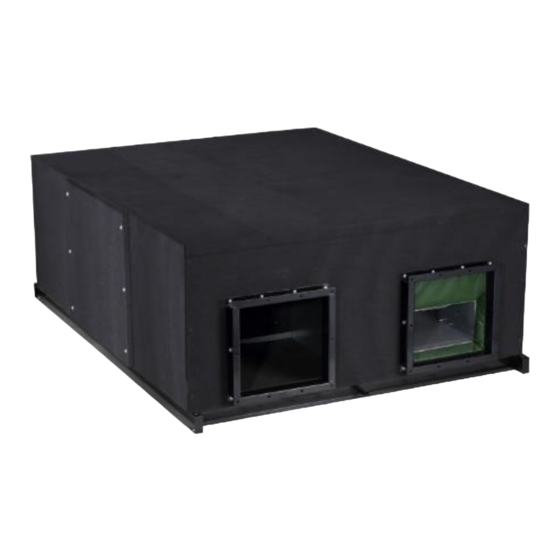
External Appearance
Features
Main Parts of the Unit
Main PCB Description
Wiring Diagrams
Specifications
Dimensions
Maintenance Spaces
Fan Performance
Electrical Characteristics
Operating Condition Limits
Installation
Wiring
Trial Run
Troubleshooting
Maintenance
Controller
Accessories
Appendix
Advertisement
Quick Links
1
Table of Contents
2
Nomenclature
3
Product Details
4
Specifications
5
Dimensions
6
Controller
7
Accessories
Download this manual
Technical Manual
DC Series HRV
HRV-D200(B)
HRV-D300(B)
HRV-D400(B)
Commercial Air Conditioners
DC 50Hz
HRV-D500(B)
HRV-D800(B)
HRV-D1000(B)
HRV-D1500(B)
HRV-D2000(B)
Table of
Contents
Previous
Page
Next
Page
1
2
3
4
5
Advertisement
Table of Contents
Need help?
Do you have a question about the DC HRV Series and is the answer not in the manual?
Ask a question
Questions and answers
Related Manuals for Midea DC HRV Series
Heating System Midea HRV-D200 Technical & Service Manual
Hrv with dc fan motor (28 pages)
Air Conditioner Midea DLCERAA12AAJ Service Manual
Dlcera series outdoor unit single zone ductless system - sizes 09 to 24 (73 pages)
Air Conditioner Midea DLCERA Series Installation Instructions Manual
Outdoor unit single zone ductless system − sizes 09 to 24 (14 pages)
Air Conditioner Midea DLCSRAH12AAJ Installation Instructions Manual
Dlcsra series, outdoor unit ductless split system (14 pages)
Air Conditioner MIdea DHMSHA Series Installation Instructions Manual
High wall ductless system (14 pages)
Air Conditioner Midea DLFSHB Manual
High wall ductless system (57 pages)
Air Conditioner Midea DLFSDA Installation Instructions Manual
Ducted style ductless system − sizes 09 to 58 (26 pages)
Air Conditioner Midea DUCMI170IHB User Manual
High static pressure duct type air conditioner (76 pages)
Air Conditioner Midea DUCMI70IB User Manual
Middle static pressure duct type air conditioner (76 pages)
Air Conditioner Midea Ducted Series User Manual
High static pressure duct type air conditioner (76 pages)
Air Conditioner Midea D5FSHAH Owner's Manual
High wall ductless system sizes 06 to 36 (16 pages)
Air Conditioner Midea M2OF-18HFN1-M Service Manual
Moovair (144 pages)
Air Conditioner Midea D5CSRA Installation Manual
Outdoor unit single zone ductless system sizes 9 to 36 (26 pages)
Air Conditioner Midea D5FSFAH Installation Instructions Manual
Floor console unit ductless system - sizes 09k to 16k (30 pages)
Air Conditioner Midea HRV-D400B Technical Manual
Commercial air conditioners (39 pages)
Air Conditioner Midea HRV-D1500B Technical Manual
Commercial air conditioners (39 pages)
This manual is also suitable for:
Hrv-d200
Hrv-d300
Hrv-d400
Hrv-d500
Hrv-d800
Hrv-d1000
...
Show all
Hrv-d1500
Hrv-d2000
Hrv-d200b
Hrv-d300b
Hrv-d400b
Hrv-d500b
Hrv-d800b
Hrv-d1000b
Hrv-d1500b
Hrv-d2000b
Table of Contents
Save PDF
Print
Rename the bookmark
Delete bookmark?
Delete from my manuals?
Login
Sign In
OR
Sign in with Facebook
Sign in with Google
Upload manual
Upload from disk
Upload from URL


Need help?
Do you have a question about the DC HRV Series and is the answer not in the manual?
Questions and answers