Page 1
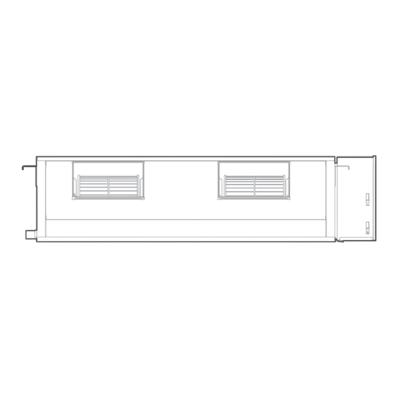
HIGH STATIC PRESSURE DUCT TYPE AIR CONDITIONER USER MANUAL MODEL NUMBER: DUCMI170IHB Warning notices: Before using this product, please read this manual carefully and keep it for future reference. The design and speci cations are subject to change without prior notice for product improvement.
THANK YOU LETTER Thank you for choosing Midea! Before using your new Midea product, please read this manual thoroughly to ensure that you know how to operate the CONTENTS THANK YOU LETTER SAFETY PRECAUTIONS SPECIFICATIONS PRODUCT OVERVIEW PRODUCT INSTALLATION Install Your Indoor Unit...
SAFETY PRECAUTIONS It’s really important you read Safety Precautions Before Operation and Installation Incorrect installation due to ignoring instructions can cause serious damage or injury. The seriousness of potential damage or injuries is classified as either a WARNING or CAUTION. Explanation of Symbols WARNING The signal word indicates a hazard with a medium level of risk...
Page 5
WARNING FOR PRODUCT USE If an abnormal situation arises (like a burning smell), immediately turn o the unit ● and disconnect the power. Call your dealer for instructions to avoid electric shock, fire or injury. Do not insert fingers, rods or other objects into the air inlet or outlet. This may ●...
Page 6
TAKE NOTE OF FUSE SPECIFICATIONS The air conditioner’s circuit board (PCB) is designed with a fuse to provide overcurrent protection. The specifications of the fuse are printed on the circuit board ,such as : T5A/250VAC, T10A/250VAC, etc. T20A/250VAC(<=24000Btu/h units), T30A/250VAC(>24000Btu/h units) NOTE: For the units with R32 or R290 refrigerant , only the blast-proof ceramic fuse can be used.
Page 7
CLEANING AND MAINTENANCE WARNINGS Turn o the device and disconnect the power before cleaning. Failure to do so ● can cause electrical shock. Do not clean the air conditioner with excessive amounts of water. ● Do not clean the air conditioner with combustible cleaning agents. Combustible ●...
PRODUCT OVERVIEW NOTE ON ILLUSTRATIONS: Illustrations in this manual are for explanatory purposes. The actual shape of your indoor unit may be slightly di erent. The actual shape shall prevail. Air outlet Air inlet Connecting pipe Air filter(optional) Outdoor Unit (A) Electric control cabinet -inside air-in grill Drain pipe...
PRODUCT INSTALLATION ACCESSORIES The air conditioning system comes with the following accessories. Use all of the installation parts and accessories to install the air conditioner. Improper installation may result in water leakage, electrical shock and fire, or cause the equipment to fail. The items are not included with the air conditioner must be purchased separately.
Page 11
INSTALLATION SUMMARY - INDOOR UNIT Install the indoor unit Install the drainpipe Install the outdoor unit Evacuate the Connect the wires Connect the refrigerant refrigeration system pipes Perform a test run...
Install Your Indoor Unit Select installation location NOTE Before installing the indoor unit, you must choose an appropriate location. The following are standards that will help you choose an appropriate location for the unit. Proper installation locations meet the following standards: Enough room exists for the There is no direct radiation Enough room exists for...
Page 13
Confirm sizes installation Installation place The distance between the mounted indoor unit should meet the specifications illlustrated in the following diagram. Strong and durable ceiling >0.8in(2cm) Indoor unit Left Right side side >0.8in(2cm) Service access Ceiling >7.9in(20cm) >11.8in(30cm) Floor Maintenance space ≥7.9in(20cm) ≥11.8in(30cm) Air outlet...
Page 14
Hang indoor unit Please refer to the following diagrams to locate the four positioning screw bolt holes on the ceiling. Be sure to mark the paces where you will drill ceiling hook holes. This unit has been installed air intake pipe flange, but there is no air filter.
Page 15
Applicable to 30~60K series only Number Name Description Gas pipe connection Ø15.9 (30~36K units) ; Ø19 or Ø22 (48~60K units) Liquid pipe connection Ø9.5 Drain pipe connection OD Ø25 ID Ø20 Using drain pump (optional) Drain pipe connection Power supply connection Air discharge flange The size of installation for indoor unit following , This unit has installed with air filter.
Page 16
Wooden structure installation 2. The installation of hanging screw bolts. Cut o the roof beam. Place the wood mounting across the roof Strengthen the area at which the cut was beam, then install the hanging screw bolts. made and consolidate the roof beam. 3.
Page 17
Step 3: Installing the main body Motor maintain: Installing the dust proof net and canvas air There are three methods: passage Type 1: 1. Install the dust proof net according to the Remove the front installation manual; side plate from the top. 2.
Page 18
Step 6: Indoor Drainpipe Installation Drill wall hole for pipe connection Install the drain pipe as illustrated in the Figure. 1. Determine the location of the wall hole Cover the drainpipe with heat insulation to prevent based on the location of the outdoor unit. condensation and leakage.
Page 19
The unit with pump. Drainpipe installation for units with a pump 1. Remove the test cover. Fill the water pan with 2 liters of water. Ceiling 1-1.5m <20cm (39-59”) Lean over 1/50 (7.9”) NOTE: When connecting multiple drainpipes, install the pipes as illustrated. The unit with pump 0-55cm (21.7”)
Page 20
Disconnect-type installation 5. Move the two boxes to the installation position (the chassis faces up and the water tray faces 1. Remove the cover of the electric control box down) and pull out the temperature sensor line and 6. Connect the temperature sensing cable / water water pump line (water distribution pump pump cable to the main board in the electric model) from the main control board.
Install Your Outdoor Unit Select installation location : PRIOR TO INSTALLATION NOTE Before installing the outdoor unit, you must choose an appropriate location. The following are standards that will help you choose an appropriate location for the unit. Proper installation locations meet the following standards: 60cm(24")...
Page 22
Install drain joint(Heat pump unit only) Base pan hole of outdoor unit Step 1: Find out the base pan hole of outdoor unit. Seal Step 2: Fit the rubber seal on the end of the drain joint that will connect to the ●...
Page 23
Anchor Outdoor Unit WARNING WHEN DRILLING INTO CONCRETE, EYE PROTECTION IS RECOMMENDED AT ALL TIME. The outdoor unit can be anchored to the ground or to a wall-mounted bracket with bolt(M10). Prepare ● the installation base of the unit according to the dimensions below. The following is a list of di erent outdoor unit sizes and the distance between their mounting feet.
Refrigerant Piping Connection When connecting refrigerant piping, DO NOT let substances or gases other than the specified refrigerant enter the unit. The presence of other gases or substances will lower the unit’s capacity, and can cause abnormally high pressure in the refrigeration cycle. This can cause explosion and injury.
Page 25
Connection Instructions—Refrigerant Piping CAUTION • The branching pipe must be installed horizontally. An angle of more than 10° may cause malfunction. • DO NOT install the connecting pipe until both indoor and outdoor units have been installed. • Insulate both the gas and liquid piping to prevent condensation. Step 1: Cut pipes Step 2: Remove burrs When preparing refrigerant pipes, take...
Page 26
(Smaller diameter) • Clamp flare from on the end of the pipe. The end of the pipe must extend beyond the flare form. (Bigger Flare form Pipe • Place flaring tool onto the form. Torque wrench • Turn the handle of the flaring tool clockwise until the pipe is fully flared.
Wiring precautions WARNING BEFORE PERFORMING ANY ELECTRICAL WORK, READ THESE WARNINGS. All wiring must comply with local and national Do not let wires touch or rest against ● ● electrical codes, regulations and must be installed refrigerant tubing, the compressor, or any by a licensed electrician.
Page 28
NOTE ON AIR SWITCH When the maximum current of the air conditioner is more than 16A, an air switch or leakage protection switch with protective device shall be used(purchased seperately). When the maximum current of the air conditioner is less than 16A, the power cord of air conditioner shall be equipped with plug (purchased seperately).
Page 29
Minimum Cross-Sectional Area of 4. Clamp down the cable with the cable clamp. Power and Signal Cables (For reference) 5. Insulate unused wires with electrical tape. Keep them away from any electrical or metal Nominal Cross-Sectional Rated Current of parts. Appliance (A) Area (mm ) 6.
Page 30
INDOOR UNIT WIRING 4. Clamp down the cable with the cable clamp. 1. Prepare the cable for connection. The cable must not be loose or pull on the a. Using wire strippers, strip the rubber jacket u-lugs. from both ends of the signal cable to reveal If there is a component of display control unit, about 15cm (5.9”) of the wire.
Page 31
Power Specifications(Not applicable for North America) NOTE Electric auxiliary heating type circuit breaker/fuse need to add more than 10 A. The circuit breaker/fuse specification shall be subject to the unit nameplate. (applicable for Australian model) Indoor Power Supply Specifications MODEL(Btu/h) ≤18K 19K~24K 25K~36K...
AIR EVACUATION NOTICE When opening valve stems, turn the hexagonal wrench until it hits against the stopper. Do not try to force the valve to open further. Close the Low Pressure side of the manifold Preparations and precautions gauge, and turn o the vacuum pump. Wait for 5 minutes, then check that there Air and foreign matter in the refrigerant circuit has been no change in system pressure.
NOTE ON ADDING REFRIGERANT CAUTION DO NOT mix refrigerant types. Some systems require additional charging depending on pipe lengths. The standard pipe length varies according to local regulations. For example, in North America, the standard pipe length is 7.5m (25’). In other areas, the standard pipe length is 5m (16‘).
TEST RUN CAUTION Failure to perform the test run may result in unit damage, property damage, or personal injury. f. Check to see that the drainage system is Before test run unimpeded and draining smoothly. g. Ensure there is no vibration or abnormal A test run must be performed after the entire noise during operation.
SPECIFICATIONS AND FEATURES Indoor unit NOTE: Di erent models have di erent display panel. Not all the indicators describing below are available for the air conditioner you purchased. Please check the indoor display panel of the unit you purchased. Illustrations in this manual are for explanatory purposes. The actual shape of your indoor unit may be slightly di erent.
Page 37
Display panel Timer Infrared indicator receiver Manual LED display button Operation Alarm indicator indicator PRE-DEF (pre-heating/defrost) indicator • MANUAL button : This button selects the mode in the following order: AUTO, FORCED COOL, OFF. FORCED COOL mode : In FORCED COOL mode, the Operation light flashes. The system will then turn to AUTO after it has cooled with a high wind speed for 30 minutes.
Page 38
Fixed-speed Type HEAT mode DRY mode COOL mode 0°C-30°C Room 17°C-32°C (62°F-90°F) 10°C-32°C (50°F-90°F) Temperature (32°F-86°F) 18°C-43°C (64°F-109°F) 11°C-43°C (52°F-109°F) -7°C-43°C (19°F-109°F) -7°C-24°C Outdoor 18°C-43°C (64°F-109°F) (For models with low-temp cooling systems) Temperature (19°F-75°F) 18°C-52°C (64°F-126°F) 18°C-52°C (64°F-126°F) (For special tropical models) (For special tropical models) NOTE: Room relative humidity less than 80%.
WIRE REMOTE CONTROLLER NOTE the wired remote controller you purchased (depend on model). The actual shape shall prevail. Read this description carefully before installing or operating your wired remote controller. KJR-120M(X4)/BGEF, KJR-120M(X4W)/BGEF, KJR-120M(X5)/BGEF, Model KJR-120M(X5W)/BGEF, KJR-120M(X6)/BGEF, KJR-120M(X6W)/BGEF, KJR-120M1(X4)/BGEF 1. Safety precaution WARNING Please entrust the distributor or professionals to install the unit.
Page 40
2. Prepare the following assemblies on the site. Qty.(embeded into wall) Specification (only for reference) Remarks Name Switch box Wiring Tube(Insulating Sleeve and Tightening Screw) 1. This manual provides the installation method of wired controller. Please refer to the wiring diagram of this installation manual to connect the wire controller with indoor unit.
Page 41
3. Fasten the back plate of the wired controller For exposed mounting, fasten the back plate on the wall with the 3 screws (ST3.9*25) and plugs. (Fig.3-3) Back plate Screws (ST3.9*25) Fig 3-3 Use two M4X25 screws to install the back cover on the 86 switch box, and use one ST3.9*25 screw to fx to the wall.
Page 42
BATTERY WARNING KEEP OUT OF REACH OF CHILDREN. Swallowing can lead to chemical burns, perforation of soft tissue, and death. Severe burns can occur within 2 hours of ingestion. Seek medical attention immediately. WARNING INGESTION HAZARD: This product contains a button cell or coin battery. DEATH or serious injury can occur if ingested.
Page 43
4. Battery installation Fig 3-5 Put the battery into the installationsite and make sure the positive side of the battery is in accordance • with the positive side of installationsite. (See Fig.3-5) Please set the time corrected on the frst time operation. Batteries in the wire controller can time under •...
Page 44
Model A Connect the wire from the display panel of the indoor unit to a connecting cable. Then connect the other side of the connecting cable to the remote control. Mainboard 4-core wire The connective wires group shielded wire(some units) Fig 3-7 Applicable to Light Commercial air conditioner Adaptor board...
Page 45
The main/secondary wired controller can be used to enable two wired controllers to control one unit, and the wired controllers connect to the unit HA and HB ports through the HA and HB port on the controller. There is no polarity between HA and HB. SeeFig. 3-10 Indoor Unit HA HB Wired Controller 1...
Page 46
6. Reattach the upper part of the wired controller After adjusting the upper case and then buckle the upper case; avoid clamping the wiring during installation. (Fig 3-13) All the pictures in this manual are for explanation purpose only. Your wire controller may be slightly diferent .The actual shape shall prevail.
Page 47
6. Name on the LCD of the wired controller °C / °F display MODE display Temperature display Room temperature display Displays the current mode,including: Relative humidity display Lock display Wireless control feature display Follow me feature display Breeze away display Delay off display Turbo feature display ECO feature display...
Page 48
8. Preparatory operation Set the current day and time Press the Timer button for 2 seconds or more. The timer display will fash. Press the button “ ” or “ ” to set the date. The selected date will fash. The date setting is fnished and the time setting is prepared after pressing Timer button or CONFIRM button or there is no pressing button in 10 seconds.
Page 49
9. Operation To set the operation mode Operation mode setting(Heat mode is invalid for cool only type unit) Press this button to select the operation mode: If the indoor unit has Electric heating(Emergent heating) feature, press this button to select the operation mode: When the mode is selected as emergency heating (or electric heating) mode, is displayed, the fan speed is Auto.
Page 50
Swing function(For the units with horizontal & vertical swing features only) 1 Up-Down swing Press the SWING button to start up-down swing function. The “ ” mark appears. Press it again to stop. 2 Left-Right swing Press the Swing button for 2 seconds to start Left-Right swing function. The “ ”...
Page 51
Intelligent eye display 1.This function is valid in any mode of power-on state. 2.When the indoor unit sending wire controller has the smart eye function, press the function key to select the smart eye icon, press the OK key to turn on the smart eye, and light up the smart eye icon at the same time;...
Page 52
10. Timer functions WEEKLY timer Use this timer function to set operating times for each day of the week. On timer Use this timer function to start air conditioner operation. The timer operatesand air conditioner operation starts after the time has passed. Of timer Use this timer function to stop air conditioner operation.
Page 53
11. Weekly Timer 1 1. Weekly timer setting Press the Timer button to select the and then press the Confrm button to confrm. 2. Day of the week setting Press the button “ ” or “ ” to select the day of the week and then press the Confrm button to confrm the setting.
Page 54
WEEKLY timer operation To activate WEEKLY TIMER operation Press the Timer button while is displayed on the LCD. To deactivate WEEKLY TIMER operation Press the Timer button while is disappear from the LCD. To turn off the air conditioner during the weekly timer 1.
Page 55
DELAY function During the weekly timer, press the FUNC. button , select the delay function and press the Confrm button,display" " " "" " and wait 3 seconds to confrm. When the delay function is activated,the “ ”mark appears. The delay function can only be enabled in Weekly Timer 1 and Weekly Timer 2. ex.
Page 56
2. Day of the week setting Press “ ” or “ ” to select the day of the week and then press CONFIRM. 3. ON timer setting of timer setting 1 Press “ ” or “ ” to select the setting time. The setting time, mode, temperature and fan speed appear on the LCD.
Page 57
WEEKLY timer operation To start Press Timer to select the , and then the timer starts automatically. To cancel Press the Power buttons for 2 seconds to cancel the timer mode. The timer mode can also be canceled by changing the timer mode using Timer. To set the DAY OFF (for a holiday) After setting the weekly timer, press CONFIRM.
Page 58
Press COPY to confrm. ex. Copy the setting of Monday to Wednesday Other days can be copied by repeating steps 4 and 5. Press CONFIRM to confrm the settings. Press BACK to revert to the weekly timer. Delete the time scale in one day. During the weekly timer setting, press CONFIRM.
Page 59
14.Technical indication and requirement EMC and EMI comply with the CE certifcation requirements. 15.Queries and settings When the air conditioning unit is switch machine, Long press “COPY” for 3 seconds , frst display P:00, if connected to an indoor unit, display P:00, if connected to multiple indoor units, press “...
Page 60
Remote control function selection of wire controller When the air conditioning unit is of, into the query function of temperature, press “ ”or “ ”to select rEC. ON or OF will be displayed in the temperature area to indicate whether it is valid or invalid. When the selection is invalid, the wire controller does not process any remote control signals.
Page 61
CAUTION Please Check The Service Website For More Information. • Smart Phone camera needs to be 5 million pixels or above to make sure scan QR code well. • Due to diferent network situation, sometimes, request time-out could happen, thus, it is necessary to •...
Page 62
Register and log in Open the MSmartHome app, and create a new account to start ( you can also register through a third-party account). If you already had an existing account, use the account to log in. Login Enter email XXXXXXXXX Login Enter password...
Page 63
5. If no message appears, select "+" on the page and select your device in the list of nearby devices available. If your device is not listed, please add your device manually by the device category. 6. Connect your device to Wireless Network according to the instructions on app. If the connection fails, please follow the instructions provided by the app to continue with the operation.
Page 64
NOTE: Make sure your devices are powered on. • Keep your mobile phone close enough to your device when you are connecting network to your device. • Connect your mobile phone to the wireless network at home, and make sure you know the password of •...
Page 65
Breezeless function of dip switch. NTOE: This feature is only available under cool mode. This feature is for some models. INDOOR UNIT MAIN BOARD SW2-1 SW2-2 SW2-2 dip switch to be “ON”,turn on the breezeless. SW2-2 dip switch to be “OFF”,turn off the breezeless.
CLEANING AND MAINTENANCE CAUTION Cleaning Your Indoor Unit • Always TURN OFF your AC system and disconnect its power supply before cleaning or maintenance. • Only use a soft, dry cloth to wipe the unit clean. You can use a cloth soaked in warm water to wipe it clean if the unit is especially dirty.
TROUBLESHOOTING CAUTION If any of the following conditions occurs, turn o your unit immediately! • The power cord is damaged or abnormally warm • You smell a burning odor • The unit emits loud or abnormal sounds • A power fuse blows or the circuit breaker frequently trips •...
Page 68
Issue Possible Causes The outdoor unit The unit will make different sounds based on its current operating mode. makes noises Dust is emitted from The unit may accumulate dust during extended periods of non-use, which will be either the indoor or emitted when the unit is turned on.
Page 69
Problem Possible Causes Solution Wait for the power to be restored Power failure The power is turned off Turn on the power The unit is not The fuse is burned out Replace the fuse working Replace batteries Remote control batteries are dead The Unit’s 3-minute protection Wait three minutes after restarting has been activated...
Page 70
Troubleshoot Your Wireless Remote Control Problem Possible Causes Solution In AUTO mode, the fan speed is Check whether AUTO set automatically and cannot be mode is selected. changed. The fan speed cannot be changed. In DRY mode, the FAN SPEED button is ineffective.
Page 71
Packing And Unpacking The Unit Instructions for packing unpacking the unit: Unpacking: Indoor unit: 1.Cut the packing belt. 2. Unpack the package. 3. Take out the packing cushion and packing support. 4. Remove the packing film. 5. Take out the accessories. 6.
Page 72
Impedance Information (Applicable to some countries of Middle East Area only) To be in compliance EN 61000-3-11, the product MTIT-30CWN1-QC5 shall be connected only to a supply of the system impedance: Zsys = 0.078 ohms or less. Before connect the product to public power network, please consult your local power supply authority to ensure the power network meet above requirement.
Midea Group and/or its a liates (“Midea”), to which Midea owns trade- marks, copyrights and other intellectual property rights, and all goodwill derived from using any part of an Midea trademark.
MideaDPO@midea.com. To exercise your rights such as right to object your personal date being processed for direct marketing purposes, please contact us via MideaDPO@midea.com. To find further information, please follow the QR Code. The design and specifications are subject to change without prior notice for product improvement.
Need help?
Do you have a question about the DUCMI170IHB and is the answer not in the manual?
Questions and answers