Table of Contents
Advertisement
Quick Links
Advertisement
Table of Contents

Related Manuals for ATESS PCS100


Summary of Contents for ATESS PCS100
- Page 1 ATESS PCS100 Bidirectional battery Inverter User Manual Shenzhen ATESS Power Technology Co.,Ltd 1st Floor of Building 3 at Sector B and 3rd Floor of Building 9, Henglong Industrial Park, No.4 Industrial Zone, Shuitian +86 755 2998 8492 +86 755 2998 5623 www.atesspower.com...
-
Page 2: Table Of Contents
7.1 Replacing the dust screen 3.3 The layout of the main components 7.2 Regular maintenance 7.3 Waste disposal 3.4 Operation mode 3.5 Battery setting 3.6 Protection Appendix 3.7 Storage 3.8 Dimension 8.1 Specification 3.9 Packaging information 8.2 ATESS Factory warranty 8.3 Contact... -
Page 3: About This Manual
1.3 How to use this Manual safety instruction Read this manual before installation of the ATESS PCS100. Store this manual where accessible at all times. Attention that needs to be paid when operating and maintaining ATESS PCS100. The contents of this manual will be periodically updated or revised if necessary. -
Page 4: Safety Instructions
The inverter should be carefully checked before signing the document from the transportation company. Check the received items against delivery note, and if there is any defect or damage, immediately notify the transportation company. If necessary, you can seek help from ATESS Customer Service department. -
Page 5: Transportation
2.6 Repair and maintenance ATESS PCS100 can only be stored when it is stopped and all the doors are closed in a dry room to protect the internal circuits Repair and maintenance can only be carried out after disconnecting the DC and AC CAUTION against dust and moisture. -
Page 6: Important Note
3.1 Energy Storage system Electromagnetic emission impact on the environment ATESS PCS100 bidirectional battery inverter is designed for energy storage system, it converts DC current generated by battery bank into AC current and feed it into the Inverter may generate some noise and electromagnetic radiation during operation. -
Page 7: The Layout Of The Main Components
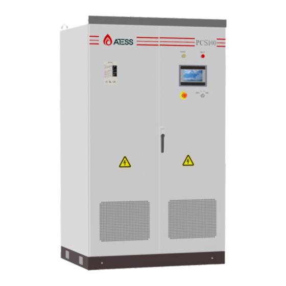
3.3 The layout of the main components Indicator There are two LED indicators on the inverter which is used to display the current 3.3.1 External components status of the inverter. External main components include: LED indicator, LCD touch screen and start-stop knob, emergency stop button, the DC side switch and the AC side switch. -
Page 8: Operation Mode
AC, DC breaker, can the inverter power and adjust its output automatically : resume working normally. 1) PCS100 connected to battery on the DC side, and load equipment on the AC side, Off-on knob make sure grid is not connected;... -
Page 9: Battery Setting
> The packaging should be restored to its original state; > Retain the desiccant in the packaging. > The ATESS PCS100 can only be stored when it is stopped and all the doors are closed in a dry room to protect the internal circuits against dust and moisture. -
Page 10: Installation Condition Requirements
In front of the installation place of inverter, a space of 1.5m or more shall be ensured, Products installation the back 0.6m or more, the top 0.6m or more to ensure easy installation, cooling and maintenance. [Cable trench] 4.1 Installation condition requirements The cable connection of inverter adopts bottom inlet and bottom outlet. -
Page 11: Tools And Spare Parts Required For Whole Machine Installation
Note 1: The inverter is integrated and cannot be dissembled either in transportation of exhaust devices; or installation. Any fault attributed to modification unauthorized by the ATESS is Another fan can be added at the air duct outlet to exhaust the air out and ensure beyond the quality assurance. - Page 12 Sign Indication Face up to prohibit the inverter horizontally, tilted or upside down Handle with care, to avoid the transport environment too intense collision friction damage to the inverter Keep away from moisture Figure 4-3-2-1 [Movement and installation of bear machine] Inverters whose packages are not demolished can be moved with forklift, hoisting crane or crane.
-
Page 13: Electrical Installation
Cable (Cu) Cable Diameter Requirements (mm²) Aperture 4.4.1 Input and output requirements Model ATESS PCS100 1 input cables with each 95 mm ,or 2 Φ10,30N*m input cables with each at least 35 mm Caution, risk of danger 1 input cables with each 95 mm ,or 2 Φ10,30N*m... - Page 14 Procedure 2: Open the front door. The unlock schema is shown in Figure 4-4-2-2. Specific procedures are as follows: 1) Cut off the distribution circuit breaker at the DC side, and ensure that no voltage on the wire at DC side. 2) Determine the positive and negative with a multimeter.
-
Page 15: Communication
GFDI device must be used for safety. 4.5 Communication The inverter of ATESS PCS series has various communication methods. When the user needs to monitor the operating status of DC power generation system, we provide Figure 4-4-4 AC Output Wiring single-machine and multi-machine control programs, and diversified communication interfaces for customer's selection. -
Page 16: Installation Inspection
Pilot operation 4.6 Installation inspection Before the inverter is put into operation, it shall be inspected for installation. Two The chapter will introduce the procedure of pilot operation, including checking working men or more shall inspect to ensure correct installation of all installation battery voltage, input and output connecting, other preparation working. -
Page 17: Power On Steps
Procedure 2: Measure whether inverter voltage, current and THD are stable. First switched on PCS100 steps are as follow: Procedure 3: Operate LCD control panel and inspect whether it displays normally Step 1: Turn AC circuit breaker handle to "ON" position. -
Page 18: Lcd Display Screen Introduction
Pressing the following key can switch to other pages. Table 6-1 ATESS PCS100 LCD Menu After powering on the LCD, it will initialize itself first, and then enter the boot which displays the progress bar of starting up. - Page 19 Time settings: system time setting (if the date and time displayed on LCD is not inconsistent with the actual date and time, they can be modified here) 6.2.3 System setting Device Information: This page shows the manufacturer, inverter serial number, hardware and software version information, and the date of manufacturing.
- Page 20 6.2.4 Historical information 6.2.5 Operation data Clicking “historical information” can enter into the sub-menu of the "historical information". Clicking the “Operation data” in any interface will enter into the submenu of History of failure: all the common history of failure details can be found by flipping “operation data”.
-
Page 21: Lcd Display Information Schedule
6.3 LCD display information schedule information AC_GridCurr_DcHigh_Fault 6.3.1 General history failure table AC_GridCurr_High_Fault AC_L_Curr_High_Fault information AC_Overload_Fault Smoke_Alarm_Fault DC_Inverse_Failure GFDI_HallSense_Fault IGBT_Failure GFDI_AirSwitch_Fault EEPROM_Write_Failure Inductor_Rly_Fault EEPROM_Read_Failure LVRT_Fault AC_MainContactor_Failure Module1_OverTemp_Fault AC_SlaveContactor_Failure Module2_OverTemp_Fault GFCI_Failure Inductor1_OverTemp_Fault GFCI_Failure Inductor2_OverTemp_Fault RISO_Failure Transformer_OverTemp_Fault DC1_VoltHigh_Fault LowTemp_Fault BAT_VoltHigh_Fault EPO_Stop BAT_CurrHigh_Fault KeyEmergencyStop BMS_Fault LcdEmergencyStop... -
Page 22: Replacing The Dust Screen
Routine maintenance information Batt_UnderVolt_Warning 7.1. Replacing the dust screen AC_WU_OverVolt_Rmt_Warning AC_WU_ UnderVolt _Rmt_Warning When the inverter fails, the inverter will automatically disconnect from the power AC_VW_ UnderVolt _Rmt_Warning grid, and display the alarm information. When there is problem with the utility grid or AC_UV_OverVolt_Rmt_Warning the inverter is disconnected manually, the inverter will shut down immediately to AC_UV_ UnderVolt _Rmt_Warning... -
Page 23: Regular Maintenance
According to environmental protection requirements, user shall dispose the inverter in accordance with the 8.2 ATESS Factory warranty relevant laws and regulations. Warranty for the ATESS inverter products Possession of this certificate validates a standard factory warranty from the date of purchase. -
Page 24: Contact
Original purchaser. Liability The liability of ATESS in respect of any defects in its DC inverters shall be limited to The warranties described in these “Limited Warranties ” are exclusive and are compliance with the obligations as stated in these terms and conditions of expressly in lieu of and exclude all other warranties, whether written, oral, express warranty.
Need help?
Do you have a question about the PCS100 and is the answer not in the manual?
Questions and answers