Table of Contents
Advertisement
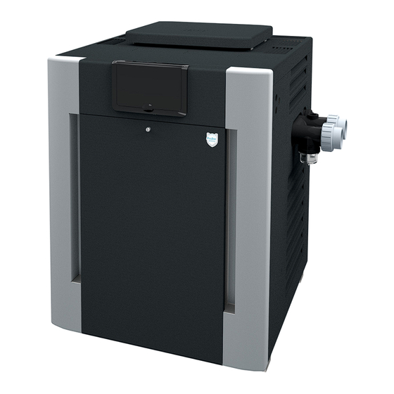
INSTALLATION AND
OPERATION MANUAL
Gas-Fired Pool
and Spa Heater
Bronze ASME and Polymer Low NOx
Heat Exchanger Models
207A, 266L, 267A, 337A, 399L, and 407A
WARNING: If the information is not followed exactly, a fire or explosion may result causing property
damage, personal injury or death.
— Do not store or use gasoline or other flammable vapors and liquids or other combustible materials
in the vicinity of this or any other appliance. To do so may result in an explosion or fire.
— WHAT TO DO IF YOU SMELL GAS
• Do not try to light any appliance.
• Do not touch any electrical switch; do not use any phone in your building.
• Immediately call your gas supplier from a neighbor's phone. Follow the gas supplier's instructions.
• If you cannot reach your gas supplier, call the fire department.
— Installation and service must be performed by a qualified installer, service agency or the gas supplier.
This manual should be maintained in legible condition and kept adjacent to the heater or in a safe place for future
reference.
Effective: 10-24-20
Replaces: 08-21-20
P/N 241793 Rev 7
A
S
M
E
HLW
ASME units only
Advertisement
Table of Contents


Need help?
Do you have a question about the 266L and is the answer not in the manual?
Questions and answers