Advertisement
Quick Links
ALI-NVR3304P, ALI-NVR3308P, ALI-NVR3316P Embedded Network Video Recorders Quick Setup Guide
This quick setup guide provides instructions to initially setup and use the ALI-NVR3304P, ALI-NVR3308P and ALI-NVR3316P network
video recorders (NVRs). For information about using your NVR and its extensive capabilities, refer to the Alibi Embedded Network Video
Recorder Firmware V3.4.x User Manual provided at www.alibisecurity.com/resources.
For more information, refer to these documents - available from your equipment vendor:
ALIBI™ Tools Utility Installation and User Manual
•
ALIBI™ Witness Smartphone App for Android - Quick Start Guide
•
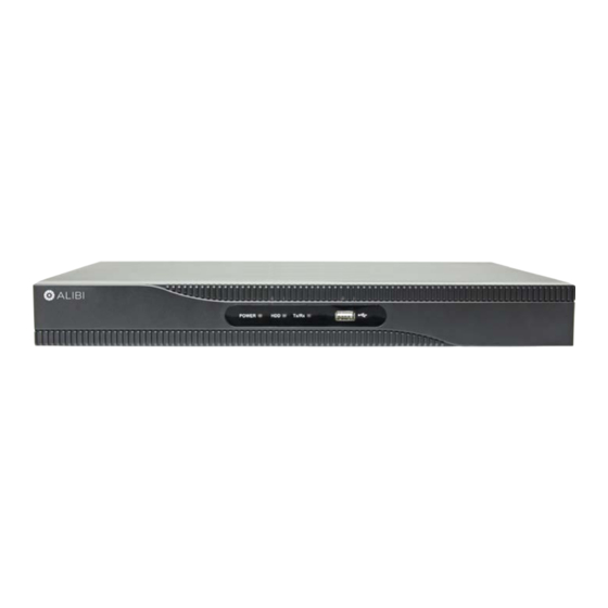
Controls and Indicators
Front panel
Status indicators USB port
Item
Function / Description
POWER
Indicator is green when the unit is powered on. When the unit is off, the LED is red if power is available.
Status Indicators
HDD
HDD indicator blinks red when data is being read from or written to an HDD.
TX/RX
Blinks green when the network connection is functioning normally.
USB Interfaces
Universal Serial Bus (USB) 2.0 port for additional USB devices such as a mouse or Hard Disk Drive (HDD).
ALI-NVR3304P
Backpanel
Audio IN/OUT
Internal Ethernet switch
ports with PoE (4)
ALI-NVR3308P
Backpanel
Internal Ethernet switch
ports with PoE (8)
1
LAN
Power switch
Video Out
Power Adapter
Ground
USB
(VGA, HDMI)
connector
terminal
Audio
Alarm
Ground
Power
IN/OUT
IN/OUT
LAN
terminal
switch
Video Out
USB
Power cord
(VGA, HDMI)
connector
ALI-NVR3316P
Backpanel
Internal Ethernet switch
ports with PoE (16)
Item
Description
VIDEO OUT (VGA, HDMI)
1 channel (HDMI/VGA). See "Specifications" on page 4 for supported output resolutions.
Audio IN / OUT
RCA connectors for audio line input and line output
Alarm IN / OUT
Terminations are provided for 4 alarm inputs (N.O. or N.C.) and 1 alarm output. See below. (ALI-NVR3308P and ALI-NVR3316P only)
ALI-NVR3304P: Connect the 48 Vdc power adapter provided with the recorder to this port, and to a standard 100 ~ 240 Vac power
source using the power cord provided.
Power connector
ALI-NVR3308P and ALI-NVR3316P: Connect the power cord provided with the recorder to this port and to a standard 100 ~ 240 Vac
power source.
ON / OFF Switch
Switch for powering the recorder on or off.
GROUND
Terminal for ground. Connect to earth ground before powering on the NVR.
LAN
10/100BASE-T (ALI-NVR3304P) or 10/100/1000BASE-T (ALI-NVR3308P and ALI-NVR3316) Ethernet network interface
Universal Serial Bus (USB) port for additional devices such as USB mouse and USB Hard Disk Drive (HDD). USB 3.0 port in ALI-NVR3308P
USB interface
and ALI-NVR3316P only.
4 (ALI-NVR3304P) or 8 (ALI-NVR3308P) or 16 (ALI-NVR3316P) 10/100 Mbps ports for IP cameras. These ports provide Power over
Internal Ethernet switch ports
Ethernet (PoE).
Alarm IN / OUT Terminals (ALI-NVR3308P and
Item
Description
ALARM IN (1 through 4 and
Alarm inputs 1 - 4. Alarm input is tied to ground at G or G terminals through the alarm sensor (N.O. or N.C.).
G, G (ground))
ALARM OUT (1 and G)
Alarm outputs 1 with ground termination.
Fan
Mouse control
outlet
A standard 3-button (left / right / scroll-wheel) USB mouse can also be used with this NVR. To use a USB mouse:
Audio
Alarm
Ground
Power
IN/OUT
IN/OUT
LAN
terminal
switch
Video Out
USB
Power cord
(VGA, HDMI)
connector
only)
ALI-NVR3316P
Fan
outlet
ALI-NVR3304-08-16P_SQ
170707
Advertisement

Related Manuals for ALIBI ALI-NVR3308P


Summary of Contents for ALIBI ALI-NVR3308P
- Page 1 10/100BASE-T (ALI-NVR3304P) or 10/100/1000BASE-T (ALI-NVR3308P and ALI-NVR3316) Ethernet network interface TX/RX Blinks green when the network connection is functioning normally. Universal Serial Bus (USB) port for additional devices such as USB mouse and USB Hard Disk Drive (HDD). USB 3.0 port in ALI-NVR3308P USB interface and ALI-NVR3316P only.
-
Page 2: Step 1. Getting Started: Unpacking The Equipment
• 6 foot HDMI cable • Wiring alarm outputs to the NVR Power cable for ALI-NVR3308P and ALI-NVR3316P, power adapter and cable for ALI-NVR3304P • HDD SATA and power interface cables for internal hard disk drive(s) • The NVR provides 1 alarm output termination that supports a DC load alarm out circuit. These terminations are marked on the back of the Remove the equipment from its packaging and place it on a flat, clean surface. - Page 3 UPS (recommended) or surge protector. Step 6. Install cameras By default, the Setup Wizard will open automatically. Refer to the Alibi Embedded Network Video Recorder Firmware V3.4.90 User Manual provided at www.alibisecurity.com/resources for incomplete instructions for using the Wizard and configuring and using your Install your security cameras.
-
Page 4: Specifications
Camera Dependent x1 (NVR) and Camera Dependent Operating System Embedded Linux For additional information about using your system, refer to the ALIBI Embedded Network Video Recorder Firmware V3.4.x User Security Password Protection Manual provided electronically with your system. IPv4, TCP/IP, UDP, HTTP, UPnP, RTSP/ Protocols TCP/IP, DHCP, DNS, DDNS, NTP, SADP, SMTP, NFS, iSCSI, UPnP™, HTTPS... -
Page 5: Hdd Installation
GreenPower™ series HDD. Security grade HDDs are designed to stream video efficiently and have a very low failure rate. HDD power cable The NVR can accommodate one HDD (ALI-NVR3304P) or two HDDs (ALI-NVR3308P and ALI-NVR3316P), each with a capacity up to 6TB. HDD SATA cable... - Page 6 During the NVR initialization, follow the options in the Wizard to initialize/reformat the HDD. You can also initialize the HDD using the Menu | HDD feature. For more information, refer to the ALIBI Embedded Network Video Recorder Firmware V3.4.x User Manual available for download from your vendor.
- Page 7 Un-package the HDD. In the photo below, note the location of the HDD mounting screw holes on the underside of the HDD. Also shown are the SATA and Power cable connectors. SATA cable connector HDD mounting screw holes Power cable connector Screw the four HDD mounting screws into the mounting screw holes until the screw heads are about 1/8 inch from the surface of the HDD.
- Page 8 Check all the HDD cable connectors to verify they are fully seated, and then reinstall the NVR top cover. When powering on the NVR, us the Alibi Wizard to initialize (Init) the HDD(s). Turn the chassis over so the top is up.
Need help?
Do you have a question about the ALI-NVR3308P and is the answer not in the manual?
Questions and answers