Table of Contents
Advertisement
ALI-NVR7232R Embedded Network Video Recorder Quick Setup Guide
This quick setup guide provides instructions to initially setup and use the ALI-NVR7232R network video recorder (NVR).
This recorder features:
Eight front-loaded HDD bays (HDDs not included)
•
HDDs are hot-swapable
•
Supports for up to 32 IP cameras
•
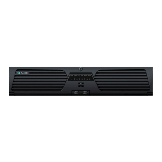
NVR Front Panel
1 .. 16 when lit, channel is active
Power button
Front panel controls and indicators
Name
Function Description
POWER
Unit is powered on.
ALARM
Turns red when a sensor alarm is detected.
TX/RX
Flashes when network connection is functioning properly.
Status Indicators
HDD
Flashes red when data is being read from or written to HDD.
READY
Ready LED is normally blue, indicating that the device is functioning properly.
ARCHIVE
Lit when a video backup / export operation is active.
1 .. 16
Channel Status indicator. Lit when channel is active.
USB 2.0 ports (2)
Universal Serial Bus (USB) ports for additional devices such as USB mouse and USB Hard Disk Drive (HDD).
1
www.Observint.com
ALI-NVR7232R front panel
Lock
Backup / Export active
USB 2.0 ports (2)
Not used
Bay 1 with HDD
Bay 2
Release button on side
Front accessible HDD bays (front panel open)
For information about using your NVR and its extensive capabilities, refer to the Alibi Embedded Network Video Recorder Firmware
V3.4.95 (or later) User Manual provided at www.alibisecurity.com/resources.
NVR Back Panel
Audio LINE IN
LAN (2)
Audio LINE
HDMI2, VGA2
VGA1, HDMI1
OUT 1, 2
Video Out
Video Out
Item
Description
eSATA
Connects external SATA HDD, CD / DVD-RM
RS-485, Alarms IN / OUT
See topic below.
Power connector
AC 100V ~ 240V power supply.
Audio LINE IN
RCA connector for audio line level input.
Audio LINE OUT 1, 2
RCA connectors for audio line level outputs.
RS-232 Interface
Connector for RS-232 devices.
VGA1, VGA2
DB9 connectors for VGA output 1, 2. Displays local video output and menus. VGA1 and VGA2 have different output format options.
HDMI1, HDMI2
HDMI video output 1, 2 connectors. HDMI1 and HDMI2 have different output format options.
USB 3.0 interface
Universal Serial Bus (USB) ports for additional devices such as USB mouse and USB Hard Disk Drive (HDD).
LAN Interface (2)
10 / 100 / 1000BASE-T network interfaces
GROUND
Ground (must be connected when NVR starts up)
ON / OFF switch
Switch for powering on / off the device.
Bay 7
Release button on side
RS-232
RS-485, Alarms IN / OUT
ON / OFF switch
eSATA
Ground
Fan outlet
Power connector
USB 3.0
Bay 8
ALI-NVR7232R_RQ
180717
Advertisement
Table of Contents

Related Manuals for ALIBI ALI-NVR7232R


Summary of Contents for ALIBI ALI-NVR7232R
- Page 1 Front accessible HDD bays (front panel open) Eight front-loaded HDD bays (HDDs not included) • For information about using your NVR and its extensive capabilities, refer to the Alibi Embedded Network Video Recorder Firmware HDDs are hot-swapable • V3.4.95 (or later) User Manual provided at www.alibisecurity.com/resources.
-
Page 2: Soft Keyboard
RS-485, ALARMS IN / OUT Soft keyboard One of two on-screen keyboards appears when you click in a field that accepts a entry, such as a password or name or a numerical value. A third keyboard which includes symbols can also be opened while in the numeric keyboard. The alphanumeric keyboard is shown in the following picture. -
Page 3: Step 1. Installing The System
Your system includes: Technologies strongly suggest that it be installed in a secure location with access limited to authorized personnel. The NVR can be installed ALI-NVR7232R NVR • on a shelf, or in a rack using the rack mounting brackets provided. -
Page 4: Wiring Alarm Outputs To The Nvr
Wiring alarm outputs to the NVR Install and setup your monitor in accordance with the instructions provided with the monitor. Do not power it on at this time. The NVR provides 4 alarm output terminations. These terminations for each output are on the ALARM OUT connector block on the back of the Cable the HDMI or VGA connector to your monitor’s VGA or HDMI input. -
Page 5: Step 2. Connecting It Together - Initial System Setup
HDD bay locations diagram After the Alibi splash screen appears (see above), the NVR will check the status of HDDs installed within the chassis, and show the show icons on the screen indicating their status. A green check mark on the icon indicates that the associated HDD is operating normally. - Page 6 After the export completes, click OK to close the Attention window. Follow the on-screen instructions provided to create a “Strong” password, and then enter that in the Create New Passw... and Confirm New Pass .. fields. Use the soft keyboards to enter the password. After entering a character string in a field, click the Enter key to move to the next field.
- Page 7 [Google] DNSs). Consult with your network administrator to determine the best network settings for your NVR. In the screen above, click Next to open the Alibi-Connect Platform Access setup page. Guiding Vision access can be used for Alibi Witness 2.0 smartphone app access by creating a direct peer to peer connection. It can also be used to download recorder firmware updates.
- Page 8 Click the star for Continuous or Motion Detection, click Yes in the Attention pop-up window, and then click OK to save the settings. The Wizard will close and the NVR will present the Live View display. See the ALIBI™ Embedded Network Video In the next window, click Search button to discover compatible cameras on the LAN to add to the system.
-
Page 9: Specifications
While viewing video from each cameras in the Live View display, adjust the direction of each camera to aim it at its surveillance target. Follow the manufacturer’s recommended procedures for aiming the cameras. For additional information about using your system, refer to the ALIBI Embedded Network Video Recorder Firmware V3.4.95 (or later) User Manual provided by your vendor. -
Page 10: Remote Client System Requirements
Video Output VGA, HDMI HDMI Video Output Formats HDMI1: 4K (3840 × 2160) / 60Hz, 4K (3840 × 2160) / 30Hz, 2K (2560 × 1440) / 60Hz, 1920 × 1080 / 60Hz, 1600 × 1200 / 60Hz, 1280 × 1024 / 60Hz, 1280 × 720 / 60Hz, 1024 ×...
Need help?
Do you have a question about the ALI-NVR7232R and is the answer not in the manual?
Questions and answers