
Related Manuals for Dukane ImagePro 6430


Summary of Contents for Dukane ImagePro 6430
- Page 1 Projector 6430/6430W/6430HD 6433/6433W User’s Manual 430-6430-6430W-6430HD-6433-6433W_User Manual-00...
- Page 2 (3) Great care has been taken in the preparation of this user’s manual; however, should you notice any questionable points, errors or omissions, please contact us. (4) Notwithstanding article (3), Dukane will not be responsible for any claims on loss of profit or othermatters deemed to result from using the Projector.
- Page 3 Important Information Safety Cautions Precautions Please read this manual carefully before using your Dukane projector and keep the manual handy for future reference. CAUTION To turn off main power, be sure to remove the plug from power outlet. The power outlet socket should be installed as near to the equipment as possible, and should be easily accessible.
- Page 4 The Federal Communications Commission does not allow any modifications or changes to the unit EXCEPT those specified by NEC/Dukane Display Solutions of America, Inc. in this manual. Failure to comply with this government regulation could void your right to operate this equipment. This equipment has been test- ed and found to comply with the limits for a Class B digital device, pursuant to Part 15 of the FCC Rules.
- Page 5 Important Information Place the projector in a horizontal position The tilt angle of the projector should not exceed 5 degrees, nor should the projector be installed in any way other than the desktop and ceiling mount, otherwise lamp life could decrease dramatically. Fire and Shock Precautions •...
- Page 6 Important Information - If the projector does not operate normally when you follow the instructions described in this user’s manual. - If the projector has been dropped or the cabinet has been damaged. - If the projector exhibits a distinct change in performance, indicating a need for service. •...
- Page 7 Important Information Health precautions to users viewing 3D images • Before viewing, be sure to read health care precautions that may be found in the user’s manual included with your LCD shutter eyeglasses or your 3D compatible content such as DVDs, video games, computer’s video files and the like.
-
Page 8: Table Of Contents
Table of Contents Table of Contents.......1 SETTING | GENERAL ......53 SETTING | SIGNAL ......56 Usage Notice ........2 SETTING | ADVANCED ....... 58 Precautions .........2 SETTING | ADVANCED | SECURITY .. 60 Introduction ........4 SETTING | ADVANCED | NETWORK .. 62 Product Features ........4 OPTIONS | GENERAL ...... -
Page 9: Usage Notice
Usage Notice Precautions Follow all warnings, precautions and maintenance as recommended in this user’s guide to maximize the life of your unit. ■ This projector will detect the life of the lamp Warning- itself. Please be sure to change the lamp when it shows warning messages. - Page 10 Usage Notice ■ Turn off the product before cleaning. ■ Use a soft cloth moistened with mild detergent to clean the display housing. ■ Disconnect the power plug from AC outlet if the product is not being used for a long period of time. ■...
-
Page 11: Introduction
Introduction Product Features ■ Supports input of High resolution Full HD (1920 x 1080) signal 0.5 W in standby condition with energy saving technology ■ Selecting [NORMAL] for [STANDBY MODE] from the menu can put the projector in power-saving mode that consumes only 0.5 W (typical value). -
Page 12: Package Overview
Introduction Package Overview This projector comes with all the items shown below. Check to make sure your unit is completed. Contact your dealer immediately if anything is missing. Projector Lens Cap Remote Control Batteries (AAAx2) Computer Cable (VGA) Security Label ... -
Page 13: Product Overview
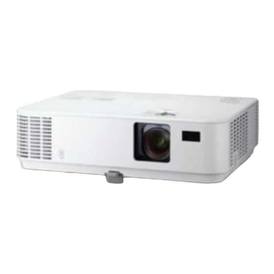
Introduction Product Overview Projector 1. Exhaust Vent 9. Tilt Foot 2. Focus Ring Release Button 3. Control Panel 10. Lens Cap 4. Zoom Lever 11. Ports 5. Intake Vent 12. Tilt Foot Security Lock Hunger 13. Kensington Lock Port 7. Remote Control Sensor 14. -
Page 14: Ports
Introduction Ports 6433/6433W/6430HD 6430/6430W 1. SERVICE Port (for service purpose only) 8. VIDEO IN Port 2. LAN Port (RJ-45) 9. AUDIO IN L/R Port 3. HDMI 2 IN Port 10. AUDIO IN Jack (3.5mm 4. HDMI 1/MHL IN or mini jack) HDMI 1 Port 11. -
Page 15: Control Panel
Introduction Control Panel 6433/6433W/6430HD 6430/6430W English ... - Page 16 Introduction VOLUME - Decrease speaker volume. Four -Use to select items For controlling the Directional or make adjustments to your speaker volume, use Select Keys selection. -Use as Quick Keys. Please see the page 13. VOLUME + Increase speaker volume. LAMP LED Indicate the projector’s lamp status.
-
Page 17: Remote Control
Introduction Remote Control POWER ON Power on the projector. Please see the “Power On/Off the Projector” section on pages 29- POWER OFF Power off the projector. Please see the “Power On/Off the Projector” section on pages 29- English ... - Page 18 Introduction COMPUTER 1 Press “1” to choose Computer IN connector. COMPUTER 2 No function. *1: Supported HDMI 1 Press “4” to choose HDMI 1/ in 6433, 6433W MHL IN connector (*1) or and 6430HD Models. HDMI1 connector (*2). VIDEO Press “VIDEO” to choose VIDEO *2: Supported in 6430, 6430W models.
- Page 19 Introduction HDMI 2 Press “5” to choose HDMI 2 IN connector. DISPLAY No function. PORT USB B No function. Number Button No function. No function. CLEAR Clear the password while you input the password. FREEZE Freeze To pause the screen image.
-
Page 20: Quick Key Activate Behavior
Introduction Quick Key Activate Behavior Quick keys are available when no OSD is displayed. The Quick Keys can be accessed on Control Panel or remote control The behavior of the Quick Keys is as described in the following tables. 6430/6430W Activate Quick Key Function... -
Page 21: Battery Installation
Introduction Battery Installation 1. Press firmly and slide the battery cover off. 2. Install new batteries (AAA). 3. Slip the cover back over the Ensure that you have the batteries until it snaps into batteries’ polarity (+/–) place. Do not mix different aligned correctly. -
Page 22: Using The Downloadable Software
Introduction Using the Downloadable Software Operating the Projector Via the LAN (Virtual Remote Tool) Using the utility software “Virtual Remote Tool” that you can download from our web site (http://www.nec-display.com/ dl/en/index.html), Virtual Remote screen (or toolbar) can be displayed on your computer screen. This will help you perform operations such as projector’s power on or off and signal selection via a LAN connection. - Page 23 Introduction Step 1: Install Virtual Remote Tool on the computer • Supported OS To install or Virtual Remote Tool will run on the following operating systems. uninstall the program, Windows 8.1 *1, Windows 8.1 Pro *1, Windows 8.1 Enterprise *1, Windows 8 *1, the Windows user Windows 8 Pro *1, Windows 8 Enterprise *1, account must have...
- Page 24 Introduction Read “END USER LICENSE AGREEMENT” carefully. 4 If you agree, click “I accept the terms in the license agreement” and then click “Next”. Follow the instructions on the installer screens to complete the installation. After the installation is completed, the shortcut icon for Virtual Remote Tool.
- Page 25 Introduction Step 3: Start Virtual Remote Tool Start using the shortcut icon Start from the Start menu Click [Start] -> [All Programs] or [Programs] -> [NEC Projector User Supportware] -> [Virtual Remote Tool] -> [Virtual Remote Tool]. When Virtual Remote Tool starts for the first time, “Easy Setup” window will be displayed.
- Page 26 Introduction Exiting Virtual Remote Tool 1 Click the Virtual Remote Tool icon on the Taskbar. The pop-up menu will be displayed. 2 Click “Exit”. The Virtual Remote Tool will be closed. Viewing the help file of Virtual Remote Tool Displaying the help file using the taskbar 1 Click the Virtual Remote Tool icon on the taskbar when Virtual Remote Tool is running.
- Page 27 Introduction Controlling the Projector over a LAN (PC Control Utility Pro 4 for Windows/PC Control Utility Pro 5 for Mac OS) [Using on Windows] Using the utility software “PC Control Utility Pro 4” that you can download from our web site (http://www.nec-display.com/dl/en/index.html), the projector can be controlled from a computer over a LAN.
- Page 28 Introduction Step 1: Install PC Control Utility Pro 4 on the computer • Supported OS - PC Control Utility Pro 4 will run on the following operating systems. Windows 8.1*1, Windows 8.1 Pro *1, Windows 8.1 Enterprise *1, Windows 8 *1, Windows 8 Pro *1, Windows 8 Enterprise *1, Windows 7 Home Basic, Windows 7 Home Premium, Windows 7 Professional, Windows 7 Enterprise, Windows 7 Ultimate Windows Vista Home Basic, Windows Vista Home Premium,...
- Page 29 Introduction Read “END USER LICENSE AGREEMENT” carefully. 4 If you agree, click “I accept the terms in the license agreement” and then click “Next”. Follow the instructions on the installer screens to complete the For the Schedule installation. function of the PC TIP:Uninstalling PC Control Utility Pro 4 Control utility Pro 4 to work, you must have...
- Page 30 Introduction 5 Click “Open” in the dialog box. If prompted, enter an administrator name and password. The installer will start. 6 Click “Next”. “END USER LICENSE AGREEMENT” screen will be displayed. 7 Read “END USER LICENSE AGREEMENT” and click “Next”. The confirmation window will be displayed.
-
Page 31: Viewing 3D Images
Introduction Viewing 3D Images The projector provides 3D images to a user wearing commercially available LCD shutter eyeglasses. CAUTION Health precautions Before viewing, be sure to read health care precautions that may be found in the user’s manual included with your LCD shutter eyeglasses or your 3D compatible content such as DVDs, video games, computer’s video files and the like. -
Page 32: Installation
Installation Connecting the Projector Connect to Computer/Notebook 6433/6433W6430HD To the wall outlet Router / Network Switch Make sure that the power plug is fully inserted into both the External projector AC IN termi- Display nal and the wall outlet. The MONITOR OUT connector supports Audio Output Separate sync signal... - Page 33 Installation 6430/6430W To the wall outlet Router / Network Switch External Display Audio Output 1.....................Power cord (supplied) 2.......................HDMI cable 3................ Computer cable (VGA) (supplied) 4........................RS232 cable 5....................... Audio cable 6....................Audio output cable 7....................VGA output cable 8........................RJ45 cable English ...
-
Page 34: Connect To Video Sources
Installation Connect to Video Sources 6433/6433W6430HD DVD Player, Set-top Box, HDTV receiver Make sure that the power plug is fully inserted into both the projector AC IN termi- nal and the wall outlet. To the wall outlet Composite Video Output Due to the difference in applications for each... - Page 35 Installation 6430/6430W DVD Player, Set-top Box, HDTV receiver To the wall outlet Composite Video Output Audio Output 1.....................Power cord (supplied) 2......................HDMI cable* 3............ 15-Pin to 3 RCA Component/HDTV Adaptor 4......................... Audio 5....................Audio Cable/RCA 6....................Audio Cable/RCA 7.................... Composite video cable *HDMI cable: Use High Speed HDMI Cable.
-
Page 36: Powering On/Off The Projector
Installation Powering On/Off the Projector Powering On the Projector 1. Securely connect the power cord and signal cable. When When you first connected, the POWER/STANDBY LED will turn Red or turn on the projec- tor, you will get the Orange (*). Startup menu. -
Page 37: Powering Off The Projector
Installation Powering Off the Projector 1. Press the “POWER OFF” button on the remote control or the button on the control panel to turn off the projector lamp, you will see a message as below on the on-screen display. While the POWER LED indicator is blink- ing green in short POWER OFF... -
Page 38: Warning Indicator
Installation Warning Indicator When the “STATUS” LED indicator flashes red, it indicates the projector has overheated. The projector will automatically shut itself down. WARNING! TEMPERATURE TOO HIGH For more informa- 1. MAKE SURE AIR IN AND OUTLETS ARE NOT BLOCKED. tion on STATUS LED 2. -
Page 39: Adjusting The Projected Image
Installation Adjusting the Projected Image Adjusting the Height of Projection Image The projector is equipped with the tilt foot for adjusting the image height. 1. Press the tilt foot release button. Keep to press the tilt foot release button for raising or lowering the projector, then lock the button by releasing it. -
Page 40: Adjusting The Projector's Focus
Installation Adjusting the Projector’s Focus To focus the image, rotate the focus ring until the image is clear. To zoom the image, turn the zoom lever in or out. Zoom Lever Focus Ring ... English... -
Page 41: Adjusting Projection Image Size (Diagonal)
Installation Adjusting Projection Image Size (Diagonal) Screen Width Screen Diagonal Screen Center Screen Bottom (α) (α α ) Lens Center B = Vertical distance between lens center and screen center. C = Throw distance. D = Vertical distance between lens center and bottom of screen (top of screen for ceiling application). - Page 42 Installation α Screen Size α (WIDE) Wide Diagonal (A) Width Height Tele Wide Tele inch inch inch inch inch inch inch mm degree degree 2540 2032 1524 3962 4368 14.2 13.0 3048 2438 1829 1188 4754 5242 14.2 13.0 3810 3048 2286 1486...
- Page 43 Installation α Screen Size α (WIDE) Wide Diagonal (A) Width Height Tele Wide Tele inch inch inch inch inch inch inch mm degree degree 6096 5169 3231 2025 8012 8788 14.2 13.0 6858 5816 3635 2278 9014 9887 14.2 13.0 7620 6462 4039...
-
Page 44: User Controls
User Controls On Screen Display The Projector has a multilingual On Screen Display that allows you to make image adjustments and change a variety of settings. How to operate To open the OSD, press the MENU button on the Remote Control. When OSD is displayed, use the buttons to select any item in the main menu. -
Page 45: Menu Tree
User Controls Menu Tree MAIN MENU SUB MENU SETTINGS PICTURE MODE PRESENTATION/HIGH-BRIGHT/VIDEO/ MOVIE/SRGB/BLACKBOARD/USER1/ USER2 WALL COLOR OFF/RED/GREEN/BLUE/CYAN/ MAGENTA/YELLOW BRIGHTNESS 0~100 GENERAL CONTRAST 0~100 SHARPNESS 0~31 SATURATION DEPEND ON SOURCE FORMAT DEPEND ON SOURCE FORMAT IMAGE GAMMA FILM/VIDEO/GRAPHICS/PC/ BLACKBOARD BRILLIANTCOL- 0~10 COLOR TEMP. - Page 46 User Controls MAIN MENU SUB MENU SETTINGS ORIENTATION DESKTOP FRONT/DESKTOP REAR/ CEILING FRONT/CEILING REAR (6430HD, 6433W, and 6433) (6430HD, 6433W, and 6433) HDMI SETTINGS -VIDEO LEVEL (AUTO/NORMAL/ ENHANCED)/ AUDIO SELECT (HDMI1 and MHL/ COMPUTER), OR HDMI2/ COMPUTER GENERAL (6430W, and 6430) (6430W, and 6430) -VIDEO LEVEL (AUTO/NORMAL/ ENHANCED)/ AUDIO SELECT...
- Page 47 User Controls MAIN MENU SUB MENU SETTINGS INPUT SEARCH ON/OFF (6430HD, 6433W, and 6433) INPUT - COMPUTER/HDMI1 and MHL/HDMI2, VIDEO (6430W, and 6430) - COMPUTER/HDMI1/HDMI2, VIDEO FAN MODE AUTO/HIGH ALTITUDE GENERAL INFORMATION ON/OFF HIDE ID DISPLAY ON/OFF BACKGROUND BLACK/BLUE COLOR RESET YES/NO LAMP LIFE RE-...
-
Page 48: Image | General
User Controls IMAGE SCREEN SETTING OPTIONS GENERAL ADVANCED PICTURE MODE PRESENTATION WALL COLOR BRIGHTNESS IMAGE | CONTRAST SHARPNESS SATURATION GENERAL SELECT EXIT MOVE MOVE COMPUTER PICTURE MODE There are many factory presets optimized for various types of images. Use the button to select the item. - Page 49 User Controls WALL COLOR Use this function to choose a proper color according to the wall. It will compensate the color deviation due to the wall color to show the correct image tone. WALL COLOR GREEN BLUE CYAN MAGENTA YELLOW BRIGHTNESS Adjust the brightness of the image.
- Page 50 User Controls SHARPNESS Adjust the sharpness of the image. Press the button to decrease the sharpness. Press the button to increase the sharpness. SHARPNESS EXIT EXIT ADJUST SATURATION Adjust a video image from black and white to fully saturated color. Press the button to decrease the amount of saturation in the ...
-
Page 51: Image | Advanced
User Controls IMAGE SCREEN SETTING OPTIONS GENERAL ADVANCED GAMMA FILM BrilliantColor™ COLOR TEMP. IMAGE | DYNAMIC CONTRAST COLOR COLOR SPACE AUTO ADVANCED SELECT EXIT MOVE MOVE COMPUTER GAMMA This allows you to choose a gamma table that has been fine-tuned to bring out the best image quality for the input. - Page 52 User Controls BrilliantColor™ This adjustable item utilizes a new color-processing algorithm and system level enhancements to enable higher brightness while providing true, more vibrant colors. The range is from “0” to “10”. If you prefer a stronger enhanced image, adjust toward the maximum setting.
- Page 53 User Controls COLOR Press ENTER into the next menu as below and then use the button to select item. COLOR RED GAIN GREEN GAIN BLUE GAIN CYAN GAIN MAGENTA GAIN YELLOW GAIN RED BIAS GREEN BIAS BLUE BIAS RESET RED GAIN ...
- Page 54 User Controls MAGENTA GAIN MAGENTA GAIN EXIT ADJUST EXIT YELLOW GAIN YELLOW GAIN EXIT ADJUST EXIT RED BIAS RED BIAS EXIT ADJUST EXIT GREEN BIAS GREEN BIAS EXIT ADJUST EXIT BLUE BIAS: BLUE BIAS EXIT ADJUST EXIT Use the...
- Page 55 User Controls RESET: Choose “YES” to return the factory default settings for color adjustments. RESET COLOR SPACE Select an appropriate color matrix type from AUTO, RGB or YUV. COLOR SPACE AUTO English ...
-
Page 56: Screen | General
User Controls IMAGE SCREEN SETTING OPTIONS GENERAL 3D SETTINGS ASPECT RATIO AUTO OVERSCAN H KEYSTONE V KEYSTONE SCREEN | GENERAL EXIT MOVE MOVE SELECT COMPUTER IMAGE SCREEN SETTING OPTIONS GENERAL 3D SETTINGS ASPECT RATIO AUTO OVERSCAN KEYSTONE EXIT MOVE MOVE SELECT COMPUTER ASPECT RATIO... - Page 57 User Controls OVERSCAN Overscan function removes the noise in a video image. Overscan the image to remove video encoding noise on the edge of video Each I/O has source. different setting of “OVERSCAN”. OVERSCAN H KEYSTONE Press the button to adjust image distortion horizontally. (This is not available on 6430 and 6430W).
-
Page 58: Screen |3D Settings
User Controls IMAGE SCREEN SETTING OPTIONS GENERAL 3D SETTINGS 3D INVERT 3D STRUCTURE FRAME PACKING SCREEN | 3D SETTINGS SELECT EXIT MOVE MOVE COMPUTER “ ” 3D INVERT Choose “ON” to turn this item on for 3D images. (default: OFF) and “... - Page 59 User Controls 3D STRUCTURE Adjust the 3D format to display 3D content correctly. 3D STRUCTURE AUTO FRAME PACKING TOP-AND-BOTTOM SIDE-BY-SIDE FRAME SEQUENTIAL TIP: 3D supported signal • For PC Signal : 1024x768@60/120Hz 1280x720@60Hz 1280x800@60/120Hz 1920x1080@60Hz • For Video Signal : 480i@60Hz •...
-
Page 60: Setting | General
User Controls IMAGE SCREEN SETTING OPTIONS GENERAL SIGNAL ADVANCED LANGUAGE ENGLISH ORIENTATION DESKTOP REAR HDMI SETTINGS MUTE VOLUME SETTING | GENERAL MOVE SELECT EXIT MOVE COMPUTER LANGUAGE Choose the multilingual OSD menu. Press the button into the sub menu and then use the button to select your preferred language. - Page 61 User Controls CEILING FRONT: When selected, the image will turn upside down. CEILING REAR This is the default selection. The image will appear reversed in upside down position. ORIENTATION DESKTOP FRONT DESKTOP REAR CEILING FRONT CEILING REAR “HDMI SETTING” ...
- Page 62 User Controls AUDIO SELECT: Use this function to select the audio souce from “HDMI1/MHL”, “HDMI2”or “COMPUTER”. AUDIO SELECT HDMI1/MHL COMPUTER AUDIO SELECT HDMI2 COMPUTER MUTE Choose “ON” to turn mute on. Choose “OFF” to turn mute off. MUTE VOLUME Press the...
-
Page 63: Setting | Signal
User Controls IMAGE SCREEN SETTING OPTIONS GENERAL SIGNAL ADVANCED PHASE CLOCK H. POSITION SETTING | V. POSITION SIGNAL SELECT EXIT MOVE MOVE COMPUTER “SIGNAL” is only supported in Analog VGA (RGB) PHASE signal. Synchronize the signal timing of the display with the graphic card. If the image appears to be unstable or flickers, use this function to correct it. - Page 64 User Controls H. POSITION Press the button to move the image left. Press the button to move the image right. H. POSITION EXIT ADJUST EXIT V. POSITION Press the button to move the image down. Press the button to move the image up.
-
Page 65: Setting | Advanced
User Controls IMAGE SCREEN SETTING OPTIONS GENERAL SIGNAL ADVANCED LOGO NETWORK SETTING | CLOSED CAPTION SECURITY TEST PATTERN ADVANCED EXIT MOVE SELECT MOVE COMPUTER LOGO Use this function to display the startup screen (NEC logo). ON: Displays the NEC logo. ... - Page 66 User Controls SECURITY OFF: Choose “OFF” to be able to switch on the projector without password verification. ON: Choose “ON” to use security verification when turning on the projector. SECURITY SECURITY KEYWORD ENTER CURRENT SECURITY CODE INVALID-KEYWORD TOO SHORT ENTER EXIT First Time:...
-
Page 67: Setting | Advanced | Security
User Controls SETTING | SECURITY ADVANCED | SECURITY SECURITY TIMER CHANGE PASSWORD SECURITY MOVE SELECT EXIT ADJUST SECURITY TIMER Use this function to set how long (MONTH/DAY/HOUR) the projector can be used. Once this time has elapsed you will be requested to enter your password again. - Page 68 User Controls 4. Use direction keys, to enter your new password and then press ENTER to confirm your password. Confirm new password CHANGE PASSWORD CONFIRM NEW SECURITY CODE ENTER EXIT 5. Enter the new password again and press ENTER to confirm.
-
Page 69: Setting | Advanced | Network
User Controls NETWORK SETTING | NETWORK STATUS DISCONNECT DHCP IP ADDRESS ADVANCED | SUBNET MASK GATEWAY NETWORK APPLY NETWORK STATUS Display the network connection status. (default: DISCONNECT) DHCP Use this function to select your desired startup screen. If you change the setting from one to another, when you exit the OSD menu, the new setting will take effect on next open. - Page 70 User Controls SUBNET MASK Select subnet mask number. SUBNET MASK MOVE SELECT EXIT ADJUST GATEWAY Select the default gateway of the network connected to the projector. GATEWAY SELECT ADJUST MOVE EXIT APPLY Press ENTER to apply the selection..English...
- Page 71 User Controls How to use web browser to control your projector 1. Turn on DHCP to allow the DHCP server to automatically assign When you used the an IP, or manually enter the required network information. projector IP address, you can not link to SECURITY KEYWORD your service server.
- Page 72 User Controls 4. Open “Projector Status and Control” to control your projector. When making a direct connection from your computer to the projector Step 1: Find an IP Address (default:192.168.0.10) from LAN function of projector. 192.168.0.10 Step 2: Select apply and press the ENTER button on the remote control or the control panel to submit function or press the MENU button on the remote control or the control panel to exit.
- Page 73 User Controls Step 4: On the General tab, under This connection uses the following items, click Internet Protocol (TCP/IP), and then click “Properties.” Step 5: Click Use the following IP address, and type in as below: 1) IP address: 192.168.0.20 2) Subnet mask: 255.255.255.0 3) Default gateway:192.168.0.1 Step 6: To open Internet Options, click IE web browser, click Internet Options, click the...
- Page 74 User Controls Step 7: The Local Area Network (LAN) Setting dialog box appears, In the Proxy Server area, cancel the Use a proxy server for your LAN check box., then click “OK” button twice. Step 8: Open your IE and type in the IP address of 192.168.0.10 in the URL then press the ENTER button key.
- Page 75 User Controls Step 9: Open “Projector Status and Control” to control your projector. English ...
-
Page 76: Options | General
User Controls IMAGE SCREEN SETTING OPTIONS GENERAL LAMP SETTINGS INPUT SEARCH INPUT FAN MODE AUTO INFORMATION HIDE OPTIONS | ID DISPLAY BACKGROUND COLOR BLUE RESET GENERAL SELECT EXIT MOVE MOVE COMPUTER INPUT SEARCH ON: The projector will search for other signals if the current ... - Page 77 User Controls 6430, 6430W INPUT COMPUTER HDMI1 HDMI2 VIDEO FAN MODE AUTO: The built-in fans automatically run at a variable speed according to the internal temperature. HIGH ALTITUDE: The built-in fans run at high speed. Select this option when using the projector at altitudes approximately 2500 feet/760 meters or higher.
- Page 78 User Controls BACKGROUND COLOR Use this feature to display a “BLACK”or “BLUE” screen when no Except signal is available. “LANGUAGE”, “LOGO”, BACKGROUND COLOR “NETWORK”, BLACK “SECURITY”, BLUE “FAN MODE”, “BACKGROUND COLOR”, “LAMP LIFE RESET REMAINING”, “LAMP HOURS Choose “YES” to return the display parameters on all menus to USED”, and the factory default settings.
-
Page 79: Options | Lamp Settings
User Controls SCREEN SETTING OPTIONS IMAGE GENERAL LAMP SETTINGS LAMP LIFE REMAINING LAMP HOURS USED ECO MODE LAMP LIFE REMINDER OPTIONS CLEAR LAMP HOURS | LAMP SELECT EXIT MOVE MOVE SETTINGS COMPUTER LAMP LIFE REMAINING Showing the Lamp life. LAMP HOURS USED Display the projection time. - Page 80 User Controls LAMP LIFE REMINDER Choose this function to show or to hide the warning message when the changing lamp message is displayed. The message will appear when the lamp has reached the end of its life. LAMP LIFE REMINDER USE THE SPECIFIED LAMP FOR SAFETY AND PERFORMANCE.
-
Page 81: Options | Information
User Controls IMAGE SCREEN SETTING OPTIONS INFORMATION ADVANCED MODEL NO. SERIAL NUMBER SOURCE OPTIONS | RESOLUTION SOFTWARE VERSION CONTROL ID INFORMATION SELECT EXIT MOVE MOVE COMPUTER COMPUTER INFORMATION To display the projector information for model no., serial number, source, resolution, and software version on the screen. English ... -
Page 82: Options | Advanced
User Controls IMAGE SCREEN SETTING OPTIONS INFORMATION ADVANCED STANDBY MODE NORMAL DIRECT POWER ON AUTO POWER OFF (MIN) OFF TIMER (MIN) OPTIONS | CONTROL PANEL LOCK CONTROL ID ADVANCED SELECT EXIT MOVE MOVE COMPUTER STANDBY MODE NETWORK STANDBY: Choose “NETWORK STANDBY” to ... - Page 83 User Controls AUTO POWER OFF (MIN) Sets the countdown timer interval. The countdown timer will start, when there is no signal being sent to the projector. The projector will automatically power off when the countdown has finished (in minutes). AUTO POWER OFF (MIN) EXIT ADJUST EXIT...
- Page 84 User Controls CONTROL ID Use this feature to display the ID number of the projector when the "ID SET" button is pressed on the remote control. CONTROL ID CONTROL ID NUMBER CONTROL ID SELECT EXIT MOVE CONTROL ID NUMBER CONTROL ID NUMBER EXIT EXIT ADJUST...
-
Page 85: Appendices
Appendices Troubleshooting If you experience trouble with the projector, refer to the following information. If the problem persists, please contact your local dealer or service center. Problem: No image appears on screen Ensure all the cables and power connections are correctly and ... - Page 86 Appendices 5. Select the “Change” under the “Monitor” tab . 6. Click on “Show all devices”. Next, select “Standard monitor types” under the SP box; choose the resolution mode you need under the “Models” box. If you are using a Notebook: ...
- Page 87 Appendices Problem: Image is out of focus Adjust the Focus Lever on the projector lens. Make sure the projection screen is between the required distance from the projector. Please see the pages 32-33). Problem: The image is stretched when displaying 16:9 DVD The projector automatically detects 16:9 DVD and adjusts the aspect ratio by digitizing to full screen with 4:3 default setting.
- Page 88 Appendices Problem: LED Indicator message POWER LED Indicator Indicator Condition Projector Condition Note The main power is off. Without connecting power cable. Blinking GREEN 0.5sec ON / 0.5sec OFF The projector is getting light ready to turn on. GREEN 2.5sec ON / 0.5sec OFF Off Timer is working.
- Page 89 Appendices LAMP LED Indicator Indicator Condition Projector Condition Note Normal Condition Blinking 0.5sec ON / 0.5sec OFF Lamp has reached its end light of life. Steady Lamp has been used beyond The projector will not light its limit. turn on until the lamp is replaced.
- Page 90 Appendices Problem: Message Reminders Over temperature - the projector has exceeded its recommended operating temperature and must be allowed to cool down before it may be used. WARNING! TEMPERATURE TOO HIGH 1. MAKE SURE AIR IN AND OUTLETS ARE NOT BLOCKED. 2.
-
Page 91: Replacing The Lamp
Appendices Replacing the lamp Optional lamp 456-6430HD (for 6433/ 6433W/6430HD 456-6430 (for 6430/6430W) The time to replace the lamp is differed from models. On 6430, and 6430W, the projectors will detect the lamp life at 4500 hours in ECO Mode Off (6000 hours in ECO Mode) On 6433, 6433W, and 6430HD, the projec- tors will detect the lamp life at 3500 hours in ECO Mode Off (6000 hours in ECO Mode). - Page 92 Appendices Warning: To reduce the risk of personal injury, do not drop the lamp module or touch the lamp bulb. The bulb may shatter and cause injury if it is dropped. Do not break the glass on the lamp module. Keep finger prints off the glass surface on the lamp module.
-
Page 93: Cleaning Procedure For The Lens
Appendices Cleaning procedure for the lens If the projection lens is dusty or blemished, please clean the lens as following procedure: 1. Turn off the projector and cool projector down for a while. 2. Unplug the power cord from outlet. 3. -
Page 94: Specifications
Appendices Specifications 6430 6430W 6433 6433W 6430HD Optical Single DLP Single DLP Single DLP Single DLP Single DLP ® ® ® ® ® chip (0.55", chip (0.65", chip (0.55", chip (0.65", chip (0.65", Projection System Aspect ratio Aspect ratio Aspect ratio Aspect ratio Aspect ratio 4:3) - Page 95 Appendices Electrical 6430 6430W 6433 6433W 6430HD Inputs 1 x VGA and Y/Pb/Pr, 2 x 1 x VGA and Y/Pb/Pr, 2 x HDMI *4 HDMI *4 (Standard HDMI (Standard HDMI connector and one with connector), 1 x VGA MHL function support), 1 x VGA Audio Audio (Stereo mini jack), 1 (Stereo mini jack), 1 x Composite Video x Composite Video (RCA...
- Page 96 Appendices *4 HDMI (Deep Color, Lip Sync) with HDCP ® What is HDCP/HDCP technology? HDCP is an acronym for High-bandwidth Digital Content Protection. High bandwidth Digital Content Protection (HDCP) is a system for preventing il- legal copying of video data sent over a High-Definition Multimedia Interface (HDMI).
- Page 97 Appendices Mechanical 6430 6430W 6433 6433W 6430HD Installation Desktop/Front, Desktop/Rear, Ceiling/Front, Ceiling/Rear Orientation Dimensions 12.8"(W) x 3.5" (H) X 9.3" (D) / 324 mm (W) x 88 mm (H) x 237 mm (D) (not including protrusions) Weight 2.7 kg/6.0lbs 2.8 kg/6.2lbs 2.9 kg/6.4lbs Environmental Operational Temperatures: 41°...
-
Page 98: Compatibility Modes
Appendices Compatibility Modes VGA Analog (1) VGA Analog - PC Signal V.Frequency H.Frequency Modes Resolution (dots) [Hz] [KHz] 640x480 31.47 640x480 37.86 640x480 37.5 640x480 43.27 SVGA 800x600 35.2 SVGA 800x600 37.88 SVGA 800x600 48.08 SVGA 800x600 46.88 SVGA 800x600 53.67 1024x768... - Page 99 Appendices (2) VGA Analog - Extended Wide timing V.Frequency H.Frequency Modes Resolution (dots) [Hz] [KHz] 1280x720 44.8 WXGA 1280x768 47.78 WXGA 1280x768 60.29 WXGA 1280x768 68.63 WXGA 1280x800 49.6 WXGA 1366x768 47.71 WXGA+ 1440x900 55.9 WSXGA 1680x1050 65.3 Full HD 1920x1080 67.5 WUXGA...
-
Page 100: Hdmi Digital
Appendices HDMI Digital Refresh Rate Signal Resolution (dots) Aspect Ratio [Hz] 640x480 59.94/60 SVGA 800x600 1024x768 *1 1280x768 15:9 WXGA 1280x800 *2 16:10 WXGA 1366x768 *4 16:9 SXGA 1280x1024 SXGA+ 1400x1050 WXGA+ 1440x900 16:10 WXGA++ 1600x900 16:9 WSXGA+ 1680x1050 16:10 UXGA 1600x1200... - Page 101 Appendices (1) HDMI - 3D Timing Resolution Aspect Refresh Rate Signal (dots) Ratio [Hz] For PC Signal 1024x768 *1 60/120 *5 1280x720 1280x720 16:9 60/120 RB *5 WXGA 1280x800 *2 16:10 60/120 RB *5 Full HD 1920x1080 *3 16:9 For Video Signal SDTV (480i) 720x480 4:3/16:9...
- Page 102 Appendices (2) MHL Signal Aspect Signal Resolution (dots) Refresh Rate (Hz) Ratio 640x480 59.94/60 HDTV (1080p) 1920x1080 16:9 23.97/24/50/59.94/60 HDTV (1080i) 1920x1080 16:9 50/59.94/60 HDTV (720p) 1280x720 16:9 50/59.94/60 SDTV (480p) 720x480 4:3/16:9 59.94/60 SDTV (576p) 720x576 4:3/16:9 SDTV (480i) 720 x 480(1440x480i) 4:3/16:9 59.94/60...
-
Page 103: Ceiling Mount Installation
Appendices Ceiling Mount Installation To refuse the projector from damage, please use the ceiling mount kit for ceiling mount installation. If you buy a ceiling mount from another company, please be sure to use the screw in correct size. Screw size is vary depending on the thickness of the mount- ing plate. -
Page 104: Cabinet Dimensions
Appendices Cabinet Dimensions Unit: mm (inch) 250,00 (9,84”) 43,41 (1,71”) 57,89 (2,28”) 88,00 (3,46”) 9,80 (0,39”) 91,50 (3.60”) ... English... -
Page 105: Pin Assignments Of D-Sub Computer Input Connector
Appendices Pin Assignments of D-Sub COMPUTER Input Connector Mini D-Sub 15 Pin Connector Pin No. RGB Signal (Analog) YCbCr Signal 11 12 13 14 15 Green 9 10 Blue Ground Ground Signal Level Red Ground Cr Ground Video signal : 0.7Vp-p (Analog) Green Gro Y Ground Sync signal : TTL level... -
Page 106: Pc Control Codes And Cable Connection
Appendices PC Control Codes and Cable Connection PC Control Codes Function Code Data POWER ON POWER OFF INPUT SELECT COMPUTER INPUT SELECT HDMI 1 INPUT SELECT HDMI 2 INPUT SELECT VIDEO PICTURE MUTE ON PICTURE MUTE OFF SOUND MUTE ON SOUND MUTE OFF NOTE: Contact your local dealer for a full list of the PC Control Codes if needed. -
Page 107: Troubleshooting Check List
Troubleshooting Check List Before contacting your dealer or service personnel, check the following list to be sure repairs are needed also by referring to the “Troubleshooting” section in your user’s manual. This checklist below will help us solve your problem more efficiently. * Print the following pages. - Page 108 In the space below please describe your problem in detail. Information on application and environment where your projector is used Projector Installation environment Model number: Screen size: inch Serial No.: Screen type: White matte Beads Polarization Date of purchase: Wide angle High contrast Lamp operating time (hours): Throw distance: feet/inch/m Eco Mode: Off Eco Orientation: Ceiling mount Desktop Information on input signal:...
-
Page 109: Register Your Projector
Please take time to register your new projector. This will insure an active warranty and your Peace of Mind program. Visit our web site at www.dukaneav.com and submit your completed form online. DUKANE CORP AV SERVICE DEPT 2900 Dukane Drive St Charles, IL 60174... - Page 110 DUKANE CORP AV SERVICE DEPT 2900 Dukane Drive St Charles, IL 60174 800-676-2487 / 630-762-4032 Fax 630-584-5156 avservice@dukane.com www.dukaneav.com 430-6430-6430W-6430HD-6433-6433W_User Manual-00...
Need help?
Do you have a question about the ImagePro 6430 and is the answer not in the manual?
Questions and answers