Table of Contents
Advertisement
Quick Links
Download this manual
See also:
Installation Manual
Advertisement
Table of Contents
Troubleshooting

Related Manuals for Dukane 6135W


Summary of Contents for Dukane 6135W
- Page 1 Portable Projector 6135W/6136 User’s Manual 6135W_6136_User Manual...
- Page 2 Ver. 1 10/14 • Apple, Mac, Mac OS, MacBook, and iMac are trademarks of Apple Inc. registered in the U.S. and other countries. • Microsoft, Windows, Windows Vista, Internet Explorer, .NET Framework and PowerPoint are either a registered trademark or trademark of Microsoft Corporation in the United States and/or other countries. •...
-
Page 3: Important Information
Important Information Safety Cautions Precautions Please read this manual carefully before using your Dukane projector and keep the manual handy for future reference. CAUTION To turn off main power, be sure to remove the plug from power outlet. The power outlet socket should be installed as near to the equipment as possible, and should be easily accessible. -
Page 4: Important Safeguards
Important Information WARNING TO CALIFORNIA RESIDENTS: Handling the cables supplied with this product will expose you to lead, a chemical known to the State of California to cause birth defects or other reproductive harm. WASH HANDS AFTER HANDLING. RF Interference (for USA only) WARNING The Federal Communications Commission does not allow any modifications or changes to the unit EXCEPT those specified by NEC Display Solutions of America, Inc. - Page 5 Important Information WARNING • Do not place any objects, which are easily affected by heat, in front of the projection window. Doing so could lead to the object melting from the heat that is emitted from the light output. • Do not use a spray containing flammable gas to get rid of accumulated dust and dirt on the filters and the projection window.
- Page 6 Important Information the projector, unplug the power cord and have the projector serviced by a qualified service personnel. • Handle the power cord carefully. A damaged or frayed power cord can cause electric shock or fire. - Do not use any power cord other than the one supplied with the projector. - Do not bend or tug the power cord excessively.
-
Page 7: Lamp Replacement
Important Information Note for US Residents The lamp in this product contains mercury. Please dispose according to Local, State or Federal Laws. Lamp Replacement • Use the specified lamp for safety and performance. • To replace the lamp, follow all instructions provided on page 122. •... -
Page 8: Power Management Function
Important Information Power management function The projector has power management functions. To reduce power consumption, the power management functions (1 and 2) are factory preset as shown below. To control the projector from an external device via a LAN or serial cable connection, use the on-screen menu to change the settings for 1 and 2. -
Page 9: Table Of Contents
Table of Contents Important Information ....................i 1. Introduction ......................1 1 What’s in the Box? ......................1 Introduction to the Projector ..................2 Features you’ll enjoy: ....................2 About this user’s manual ..................3 Part Names of the Projector ..................4 Top and Screen Side of Projector ................ - Page 10 Table of Contents Pincushion ......................31 Preventing the Unauthorized Use of the Projector [SECURITY] ........33 Using the Computer Cable (VGA) to Operate the Projector (Virtual Remote Tool) ..36 Operating Your Computer’s Mouse Functions from the Projector’s Remote Control via the USB Cable (Remote Mouse Function) ............42 ...
- Page 11 Table of Contents [SOURCE(1)] ....................... 100 [SOURCE(2)] ....................... 100 [WIRED LAN] ....................... 100 [WIRELESS LAN] ....................101 [VERSION] ......................101 [OTHERS] ......................101 Menu Descriptions & Functions [RESET] ..............102 Returning to Factory Default [RESET] ..............102 6. Installation and Connections ..............
-
Page 12: Introduction
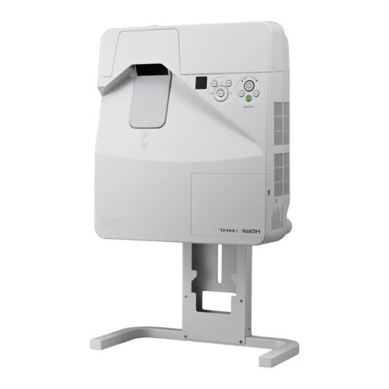
• Important Infomation (For North America: 7N8N5231) (For Other countries than North America: 7N8N5231 and 7N8N5241) • Quick Setup Guide (7N8N5251)/ (7N8N5261) Unless otherwise described in the user’s manual, the drawings for the projector cabinet show examples of the 6135W. -
Page 13: Introduction To The Projector
Ultra short focal lenses provide for a larger image using a shorter throw distance when compared to a typical projector lens. 6136: Max 116.6" (6135W: Max 110"), throw distance: 51 cm/20 inches (The throw distance refers to the distance between the screen and the screen side of the projector) •... -
Page 14: About This User's Manual
• Software programs (User Supportware) contained in the supplied CD-ROM The supplied Dukane Projector includes three programs: Virtual Remote Tool, Image Express Utility Lite (for Windows/ Mac OS), and PC Control Utility Pro 4 (for Windows)/5 (for Mac OS). Image Express Utility Lite (for Windows) can be started from a commercially available USB memory or SD card without the need of installing on your computer. -
Page 15: Part Names Of The Projector
1. Introduction Part Names of the Projector Top and Screen Side of Projector Projection Window Intake Vent/Filter (→ page 118, 125) Security chain opening Monaural Speaker (20 W) Attach an anti-theft device. The security chain opening accepts security wires or chains up to 0.18 inch/4.6 mm in diameter. -
Page 16: Removing And Attaching The Cable Cover
1. Introduction Removing and Attaching the Cable Cover After finishing connections, attach the supplied cable cover to properly hide the cables. CAUTION: • Be sure to tighten the screws after attaching the cable cover. Failure to do so may cause the cable cover to come off and fall, resulting in injury or damage to the cable cover. - Page 17 1. Introduction Attaching the cable cover 1. Align four tabs of the cable cover with grooves of the pro- jector and push the cable cover until you click it. NOTE: • Be careful not to get cables caught in between the cable cover and the projector. 2. Tighten the cable cover screws. • Be sure to tighten the screws.
-
Page 18: Top Features
1. Introduction Top Features 1, 2 (POWER) Button (→ page 14, 24) 2. POWER Indicator (→ page 13, 14, 24, 128) 3. STATUS Indicator (→ page 128) 4. LAMP Indicator (→ page 122, 128) 5. ECO Button (→ page 27) 6. -
Page 19: Terminal Panel Features
1. Introduction Terminal Panel Features 1. COMPUTER IN/ Component Input Terminal (Mini D-Sub 15 Pin) (→ page 106, 110, 113) 2. COMPUTER AUDIO IN Mini Jack (Stereo Mini) (→ page 106, 107, 110) 3. HDMI 1/MHL IN Terminal (Type A) (→... -
Page 20: Part Names Of The Remote Control
1. Introduction Part Names of the Remote Control 10. DisplayPort Button (→ page 16) 11. VIDEO Button (→ page 16) 12. USB-A Button (→ page 16, 66, 68) 13. USB-B Button (→ page 16, 106) 14. LAN Button (→ page 16) 15. -
Page 21: Battery Installation
1. Introduction Battery Installation Press firmly and slide the battery Install new batteries (AAA). Ensure Slip the cover back over the bat- cover off. that you have the batteries’ polarity teries until it snaps into place. Do (+/−) aligned correctly. not mix different types of batteries or new and old batteries. -
Page 22: Software Included On Cd-Rom
1. Introduction Software Included on CD-ROM Names and Features of Bundled Software Programs Name of software program Features Virtual Remote Tool This is a software program used to control the power ON/OFF and source selec- (Windows only) tion of the projector from your computer by using the supplied computer cable (VGA) and others. -
Page 23: Projecting An Image (Basic Operation)
2. Projecting an Image (Basic Operation) This section describes how to turn on the projector and to project a picture onto the screen. 1 Flow of Projecting an Image Step 1 • Connecting your computer / Connecting the power cord (→ page 13) Step 2 •... -
Page 24: Connecting Your Computer/Connecting The Power Cord
2. Projecting an Image (Basic Operation) Connecting Your Computer/Connecting the Power Cord 1. Connect your computer to the projector. This section will show you a basic connection to a computer. For information about other connections, see “6. Installation and Connections” on page 106. Connect the computer cable (VGA) between the projector’s COMPUTER IN terminal and the computer’s port (mini D-Sub 15 Pin). -
Page 25: Turning On The Projector
2. Projecting an Image (Basic Operation) Turning on the Projector (POWER) button on the projector cabinet • Press the or the POWER ON button on the remote control. The POWER indicator will blink and the projector will be- come ready to use. TIP: • When the message “Projector is locked! Enter your password.”... -
Page 26: Note On Startup Screen (Menu Language Select Screen)
2. Projecting an Image (Basic Operation) Note on Startup screen (Menu Language Select screen) When you first turn on the projector, you will get the Startup menu. This menu gives you the opportunity to select one of the 30 menu languages. To select a menu language, follow these steps: 1. -
Page 27: Selecting A Source
2. Projecting an Image (Basic Operation) Selecting a Source Selecting the computer or video source NOTE: Turn on the computer or video source equipment connected to the projector. Detecting the Signal Automatically Press the SOURCE button once.The projector will search for the available input source and display it. The input source will change as follows: COMPUTER →... -
Page 28: Adjusting The Picture Size And Position
2. Projecting an Image (Basic Operation) Adjusting the Picture Size and Position Use the adjustable tilt foot, the zoom function or the focus ring to adjust the picture size and position. In this chapter drawings and cables are omitted for clarity. Adjusting horizontal/vertical position Adjusting the focus [Focus ring] (→... -
Page 29: Adjusting Horizontal/Vertical Position
2. Projecting an Image (Basic Operation) Adjusting horizontal/vertical position The throw distance can affect the size and the height of the projected image. Before installing the projector, decide the throw distance according to “Setting Up the Screen and the Projector” (→ page 103, 104) It is recommended to display the test pattern while adjusting the image. -
Page 30: Adjusting The Tilt (Tilt Foot)
2. Projecting an Image (Basic Operation) Adjusting the tilt (Tilt foot) Adjusting the left and right tilt. 1. Rotate the tilt foot to adjust the left and right tilt. The tilt foot is equipped at the left and the right front bottom of the projector. -
Page 31: Adjusting The Size [Digital Zoom]
2. Projecting an Image (Basic Operation) Adjusting the size [Digital Zoom] Use the remote control to finely adjust the size of the image. 1. Press the FOCUS/ZOOM button on the remote control. The DIGITAL ZOOM bar will be displayed. 2. Press the or button to finely zoom in or out. 3. -
Page 32: ❻ Correcting Keystone Distortion [Keystone]
2. Projecting an Image (Basic Operation) ❻ Correcting Keystone Distortion [KEYSTONE] When the projector is not exactly perpendicular to the screen, keystone distortion occurs. To overcome it, you can use the “Keystone” function, a digital technology that can adjust for keystone-type distortion, resulting in a crisp, square image. - Page 33 2. Projecting an Image (Basic Operation) 4. Press the ▲ button to select [HORIZONTAL] and then use the ◀ or ▶ so that the top and bottom sides of the projected image are parallel. • Adjust the horizontal keystone distortion. 5.
-
Page 34: Optimizing Computer Signal Automatically
2. Projecting an Image (Basic Operation) Optimizing Computer Signal Automatically Adjusting the Image Using Auto Adjust Optimizing a computer image automatically. (COMPUTER) Press the AUTO ADJ. button to optimize a computer image automatically. This adjustment may be necessary when you connect your computer for the first time. [Poor picture] [Normal picture] NOTE:... -
Page 35: Turning Off The Projector
2. Projecting an Image (Basic Operation) Turning off the Projector To turn off the projector: 1. First, press the (POWER) button on the projector cabinet or the STANDBY button on the remote con- trol. The confirmation message will be displayed. Power On Standby 2. -
Page 36: When Moving The Projector
2. Projecting an Image (Basic Operation) When Moving the Projector Preparation: Make sure that the projector is turned off. 1. Remove the cable cover. (→ page 5) 2. Unplug the power cord. 3. Disconnect any other cables. • Remove the USB memory or the wireless LAN Unit if it is inserted into the projector. (→... -
Page 37: Convenient Features
3. Convenient Features 1 Turning off the Image and Sound Press the AV-MUTE button to turn off the image and sound for a short period of time. Press again to restore the image and sound. The projector’s power-saving function will work 10 seconds after the image is turned off. -
Page 38: Changing Eco Mode/Checking Energy-Saving Effect
3. Convenient Features 2. Press the button. The area of the magnified image will be moved 3. Press the D-ZOOM (−) button. Each time the D-ZOOM (−) button is pressed, the image is reduced. NOTE: • The image will be magnified or demagnified at the center of the screen. • Displaying the menu will cancel the current magnification. ... -
Page 39: Checking Energy-Saving Effect [Carbon Meter]
3. Convenient Features NOTE: • The [ECO MODE] can be changed by using the menu. Select [SETUP] → [GENERAL] → [ECO MODE]. • The lamp life remaining and lamp hours used can be checked in [USAGE TIME]. Select [INFO.] →[USAGE TIME]. • The projector is always in [NORMAL] for 90 seconds after the lamp is turned on and while the POWER indicator is blinking green. The lamp condition will not be affected even when [ECO MODE] is changed. • After a lapse of 1 minute from when the projector displays no-signal guidance, a blue, black or logo screen, [ECO MODE] will automatically switch to [ECO]. The projector will return to its original setting once a signal is accepted. • If the projector is overheated in [OFF] mode, there may be a case where the [ECO MODE] automatically changes to [NORMAL] mode to protect the projector. When the projector is in [NORMAL] mode, the picture brightness decreases. When the projector comes back to normal temperature, the [ECO MODE] returns to its original setting. Thermometer symbol [ ] indicates the [ECO MODE] is automatically set to [NORMAL] mode because the internal temperature is too high. • Immediately after [ECO MODE] is changed from [ECO] to one of [OFF], [AUTO ECO], or [NORMAL], the lamp brightness may decrease temporarily. This is not a malfunction. Checking Energy-Saving Effect [CARBON METER] This feature will show energy-saving effect in terms of CO emission reduction (kg) when the projector’s [ECO MODE] is set to [AUTO ECO], [NORMAL], or [ECO]. -
Page 40: ❺ Using 4-Point Corner To Correct Keystone Distortion [Cornerstone]
3. Convenient Features ❺ Using 4-Point Corner to Correct Keystone Distortion [CORNERSTONE] Use the [CORNERSTONE] and [PINCUSHION] features to correct keystone (trapezoidal) distortion to make the top or bottom and the left or right side of the screen longer or shorter so that the projected image is rectangular. Cornerstone 1. - Page 41 3. Convenient Features 7. Use the ▲▼◀▶ button to move the projected image frame as shown on the example. 8. Press the ENTER button. 9. Use the ▲▼◀▶ button to select another icon which points in the direction. On the Cornerstone adjustment screen, select [EXIT] or press the EXIT button on the remote control. The confirmation screen is displayed.
-
Page 42: Pincushion
3. Convenient Features Pincushion 1. Press the KEYSTONE button with no menu displayed. The KEYSTONE screen will be displayed. • Press the KEYSTONE button when using the remote control. 2. Press the button to select either PINCUSHION ADJUSTMENT LEFT/RIGHT or PINCUSHION ADJUSTMENT TOP/BOTTOM. - Page 43 3. Convenient Features 2. Move the cursor onto YES using either or button and then press the ENTER. NOTE: • All adjusted values set in the KEYSTONE adjustment are reset to initial values TIP: Adjustable range of the KEYSTONE and the CORNERSTONE: Horizontal Direction Vertical Direction CORNERSTONE Approx. ±10° (Max) Approx. ±10° (Max) KEYSTONE Adjustable range may be narrower depending on input signal.
-
Page 44: Preventing The Unauthorized Use Of The Projector [Security]
3. Convenient Features Preventing the Unauthorized Use of the Projector [SECURITY] A keyword can be set for your projector using the Menu to avoid operation by an unauthorized user. When a keyword is set, turning on the projector will display the Keyword input screen. Unless the correct keyword is entered, the pro- jector cannot project an image. - Page 45 3. Convenient Features 7. Type in the same combination of buttons and press the ENTER button. The confirmation screen will be displayed. 8. Select [YES] and press the ENTER button. The SECURITY function has been enabled. To turn on the projector when [SECURITY] is enabled: 1.
- Page 46 3. Convenient Features To disable the SECURITY function: 1. Press the MENU button. The menu will be displayed. 2. Select [SETUP] → [INSTALLATION] → [SECURITY] and press the ENTER button. The OFF/ON menu will be displayed. 3. Select [OFF] and press the ENTER button. The SECURITY KEYWORD screen will be displayed.
-
Page 47: Using The Computer Cable (Vga) To Operate The Projector (Virtual Remote Tool)
Using the Computer Cable (VGA) to Operate the Projector (Virtual Remote Tool) Using the utility software “Virtual Remote Tool” included on the companion Dukane Projector CD-ROM, Virtual Remote screen (or toolbar) can be displayed on your computer screen. This will help you perform operations such as projector’s power on or off and signal selection via the computer cable (VGA), serial cable, or LAN connection. - Page 48 The Microsoft .NET Framework Version 2.0, 3.0 or 3.5 is available from Microsoft’s web page. Download and install it on your computer. • Logo data (graphics) that can be sent to the projector with Virtual Remote Tool has the following restrictions: (Only via serial or LAN connection) - File size: Less than 1 MB - Image size (resolution): 6136 UM351W/UM301W : Horizontal 1280 × vertical 800 dots or less 6135W - Number of colors: 256 colors or less • To put the default "NEC logo" back in the background logo, you need to register it as the background logo by using the image file (UM351W/UM301W: /Logo/necpj_bbwx.bmp, UM361X/UM301X: /Logo/necpj_bb_x.bmp)inclulded on the supplied NEC Projector CD-ROM. TIP: • The projector’s COMPUTER IN terminal supports DDC/CI (Display Data Channel Command Interface). DDC/CI is a standard interface for bidirectional communication between display/projector and computer.
- Page 49 3. Convenient Features TIP: If the menu window will not be displayed, try the following procedure. For Windows 7 1. Click “start” on Windows. 2. Click “All Programs” → “Accessories” → “Run”. 3. Type your CD-ROM drive name (example: “Q:\”) and “LAUNCHER.EXE” in “Name”. (example: Q:\ LAUNCHER.EXE) 4. Click “OK”. The menu window will be displayed. 2 Click “Install Virtual Remote Tool”...
- Page 50 3. Convenient Features TIP: Uninstalling Virtual Remote Tool Preparation: Exit Virtual Remote Tool before uninstalling. To uninstall Virtual Remote Tool, the Windows user account must have “Administrator” privilege (Windows 8.1, Windows 8, Windows 7 and Windows Vista) or “Computer Administrator” privilege (Windows XP).
- Page 51 3. Convenient Features Step 3: Start Virtual Remote Tool Start using the shortcut icon • Double-click the shortcut icon on the Windows Desktop. Start from the Start menu • Click [Start] → [All Programs] or [Programs] → [NEC Projector User Supportware] → [Virtual Remote Tool] →...
- Page 52 3. Convenient Features Exiting Virtual Remote Tool 1 Click the Virtual Remote Tool icon on the Taskbar. The pop-up menu will be displayed. 2 Click “Exit”. The Virtual Remote Tool will be closed. Viewing the help file of Virtual Remote Tool •...
-
Page 53: Operating Your Computer's Mouse Functions From The Projector's Remote Control
3. Convenient Features Operating Your Computer’s Mouse Functions from the Projector’s Remote Control via the USB Cable (Remote Mouse Function) The built-in remote mouse function enables you to operate your computer’s mouse functions from the supplied remote control when the projector is connected to a computer via a commercially available USB cable (compatible with USB 2.0 specifications). -
Page 54: (Usb Display)
3. Convenient Features Projecting Your Computer’s Screen Image from the Projector via the USB Cable (USB Display) Using a commercially available USB cable (compatible with USB 2.0 specifications) to connect the computer with the projector allows you to send your computer screen image to the projector for displaying. Power On/Off and source selection of the projector can be done from your computer without connecting a computer cable (VGA). - Page 55 3. Convenient Features 5. Operate the control window. (Source) ����� Selects an input source of the projector� (Picture) ���� Turns on or off AV-MUTE (Picture mute), and turns on or off FREEZE (Freeze a picture)� (Sound) ����� Turns on or off AV-MUTE (Sound mute), play the sound and turns up or down the volume� (Others) �����...
-
Page 56: Controlling The Projector By Using An Http Browser
3. Convenient Features Controlling the Projector by Using an HTTP Browser Overview The HTTP Server function provides settings and operations for: 1. Setting for wired/wireless network (NETWORK SETTINGS) To use wireless LAN connection, the optional USB Wireless LAN Unit is required. (→ page 115) To use wired/wireless LAN connection, connect the projector to the computer with a commercially available LAN cable. -
Page 57: Handling Of The Address For Operation Via A Browser
3. Convenient Features Handling of the Address for Operation via a Browser Regarding the actual address that is entered for the address or entered to the URL column when operation of the pro- jector is via a browser, the host name can be used as it is when the host name corresponding to the IP address of the projector has been registered to the domain name server by a network administrator, or the host name corresponding to the IP address of the projector has been set in the “HOSTS”... - Page 58 3. Convenient Features PICTURE: Controls the video adjustment of the projector. CONTRAST �������� Increases the contrast adjustment value� CONTRAST �������� Decreases the contrast adjustment value� BRIGHTNESS ���� Increases the brightness adjustment value� BRIGHTNESS ���� Decreases the brightness adjustment value� SHARPNESS ...
-
Page 59: Network Settings
3. Convenient Features NETWORK SETTINGS • SETTINGS WIRED or WIRELESS SETTING Set for wired LAN or for wireless LAN. APPLY Apply your settings to wired LAN or wireless LAN. DHCP ON Automatically assign IP address, subnet mask, and gateway to the projector from your DHCP server. - Page 60 3. Convenient Features SITE SURVEY Displays a list of available SSIDs for wireless LAN on site. Select an SSID which you can access. SECURITY TYPE Turn on or off the encryption mode for secure transmission. When turn on the encryp- tion mode, set WEP key or encrypted key.
- Page 61 3. Convenient Features • ALERT MAIL ALERT MAIL (English This option will notify your computer of lamp replace time or error messages via e-mail only) when using wireless or wired LAN. Placing a checkmark will turn on the Alert Mail feature. Clearing a checkmark will turn off the Alert Mail feature.
- Page 62 3. Convenient Features • ROOMVIEW for managing from the computer. DISABLE Disables ROOMVIEW. ENABLE Enables ROOMVIEW. • CRESTRON CONTROL for managing from the controller. DISABLE Disables CRESTRON CONTROL. ENABLE Enables CRESTRON CONTROL. IP ADDRESS Set your IP address of CRESTRON SERVER. IP ID Set your IP ID of CRESTRON SERVER.
-
Page 63: Controlling The Projector Over A Lan (Pc Control Utility Pro 4/Pro 5)
3. Convenient Features Controlling the Projector over a LAN (PC Control Utility Pro 4/ Pro 5) Using the utility software “PC Control Utility Pro 4” and “PC Control Utility Pro 5” included on the companion NEC Projector CD-ROM, the projector can be controlled from a computer over a LAN. PC Control Utility Pro 4 is a program compatible with Windows. - Page 64 3. Convenient Features TIP: If the menu window will not be displayed, try the following procedure. For Windows 7: 1. Click “start” on Windows. 2. Click “All Programs” → “Accessories” → “Run”. 3. Type your CD-ROM drive name (example: “Q:\”) and “LAUNCHER.EXE” in “Name”. (example: Q:\ LAUNCHER.EXE) 4. Click “OK”. The menu window will be displayed. 2 Click “PC Control Utility Pro 4”...
- Page 65 3. Convenient Features Step 2: Connect the projector to a LAN. Connect the projector to the LAN by following the instructions in “Connecting to a Wired LAN” (→ page 114), “Con- necting to a Wireless LAN (Optional: NP05LM series)” (→ page 115) and “ Controlling the Projector by Using an HTTP Browser”...
- Page 66 3. Convenient Features Using on Mac OS Step 1: Install PC Control Utility Pro 5 on the computer 1. Insert the accompanying NEC Projector CD-ROM in your Mac CD-ROM drive. The CD-ROM icon will be displayed on the desktop. 2. Double-click the CD-ROM icon. The CD-ROM window will be displayed.
-
Page 67: Projecting Your Computer's Screen Image From The Projector Over A Lan
3. Convenient Features Projecting Your Computer’s Screen Image from the Projector over a LAN (Image Express Utility Lite) Using Image Express Utility Lite contained on the supplied NEC Projector CD-ROM allows you to send the computer’s screen image to the projector over a USB cable or a wired or wireless LAN. Image Express Utility Lite is a program compatible with Windows. - Page 68 3. Convenient Features TIP: If the menu window will not be displayed, try the following procedure. For Windows 7: 1. Click “start” on Windows. 2. Click “All Programs” → “Accessories” → “Run”. 3. Type your CD-ROM drive name (example:“Q:\”) and “LAUNCHER.EXE” in “Name”. (example: Q:\LAUNCH- ER.EXE) 4. Click “OK”. The menu window will be displayed. 2.
- Page 69 3. Convenient Features 3. Place a check mark for projectors to be connected, and then click “Connect”. • When one or more projectors are displayed, from the menu on the projector, select [INFO.] → [WIRELESS LAN] → [IP ADDRESS]. When connecting with the projector is established, you can operate the control window to control the projector. (→ page 44) NOTE: • When [NORMAL] is selected for [STANDBY MODE] from the menu, the projector that is turned off will not be displayed in the...
-
Page 70: Starting Image Express Utility Lite From A Usb Memory Or Sd Card
3. Convenient Features Starting Image Express Utility Lite from a USB Memory or SD Card Image Express Utility Lite can be started from commercially available removable media such USB memory or SD cards if it is copied beforehand. This will eliminate the trouble of installing Image Express Utility Lite to your computer. 1. - Page 71 3. Convenient Features Using on Mac OS Step 1: Install Image Express Utility Lite for Mac OS on the computer 1. Insert the accompanying NEC Projector CD-ROM in your Mac CD-ROM drive. The CD-ROM icon will be displayed on the desktop. 2.
-
Page 72: Projecting An Image From An Angle
3. Convenient Features Projecting an Image from an Angle (Geometric Correction Tool in Image Express Utility Lite) The Geometric Correction Tool (GCT) function allows you to correct distortion of images projected even from an angle. What you can do with GCT •... - Page 73 3. Convenient Features 3. Use the mouse to click the [ • ] mark of which corner you wish to move. The currently selected [ • ] mark will turn red. (In the above example, Windows screens are omitted for clarification.) 4.
-
Page 74: Connecting Your Microphone
3. Convenient Features Connecting Your Microphone Connecting a commercially available dynamic microphone or condenser mic to the MIC input jack allows you to output your mic sound from the built-in speaker. Sound input from all input terminals including LAN, USB-A, and USB-B will be heard from the speaker with your microphone voice. -
Page 75: Using The Viewer
4. Using the Viewer ❶ What you can do with the Viewer The Viewer has the following features. • When a commercially available USB memory that stores image files is inserted into the USB port (Type A) of the projector, the Viewer allows you to view the image files on the USB memory. Even if no computer is available, presentations can be conducted simply with the projector. - Page 76 4. Using the Viewer NOTE • The USB port of the projector does not support USB hub. • The following operations by using the buttons on the projector are not possible when the VIEWER screen such as the slide screen and the thumbnail screen is displayed. Buttons on the cabinet - Keystone correction by using the ▲/▼ button - Auto Adjustment by using the AUTO ADJ. button - Volume control with the ◀ or ▶ button To perform Keystone correction or Source selection during display of the Viewer, press the MENU button twice to display the menu and operate Viewer from the menu. Remote control - Auto Adjustment button - Freeze button • Executing [RESET] → [ALL DATA] from the menu will return the settings for the Viewer toolbar to the factory default. • USB memory - Be sure to use a USB memory device formatted with the FAT32 or FAT16 file system. The projector does not support NTFS formatted USB memory. If the projector does not recognize your USB memory, check if the format is supported. To format your USB memory in your computer, refer to the document or help file that comes with your Windows. - We do not warrant that the USB port of the projector will support all USB memories in the market. • Supported images - Supported file format for Viewer are as follows.
-
Page 77: ❷ Projecting Images Stored In A Usb Memory Device
4. Using the Viewer ❷ Projecting images stored in a USB memory device This section explains the basic operation of the Viewer. The explanation provides the operational procedure when the Viewer toolbar (→ page 69) is set to the factory de- fault. - Page 78 4. Using the Viewer 4. Press the ENTER button. The thumbnail screen will be displayed. (→ page 70) 5. Use the ▲▼◀ or ▶ button to select an icon. • The → (arrow) symbol on the right indicates there are more pages.
-
Page 79: Exiting The Viewer
4. Using the Viewer Removing the USB memory from the projector 1. Select the VIEWER start screen. Press the EXIT button with no menu displayed. 2. Remove the USB memory from the projector. Make sure that the LED on the USB memory is not flashing before removing the USB memory. - Page 80 • The maximum number of image files or folders within one page is different depending on the model. 6136 are 5 by 4 6135W are 6 by 4 The cursor is used to select (highlight) the folder or image file by using ▲▼◀▶ but- (4) Cursor ton.
-
Page 81: Using The Toolbar
4. Using the Viewer Using the toolbar 1. Press the MENU button. The toolbar will be displayed. The SOURCE screen will be displayed as Viewer connection screen. 2. Use the ◀ or ▶ button to select an item and use the ▲ or ▼ button to select its available option. When the cursor is placed, the selected item will be changed to yellow. - Page 82 4. Using the Viewer Slide toolbar Menu Options Description (1) Display Closes the menu and switches to the slide screen. Closes the menu and displays the thumbnail screen. Closes the menu and starts the slideshow from the highlighted item. (2) Image Closes the menu and displays the image in its actual size.
-
Page 83: Using On-Screen Menu
5. Using On-Screen Menu 1 Using the Menus NOTE: The on-screen menu may not be displayed correctly while interlaced motion video image is projected. 1. Press the MENU button on the remote control or the projector cabinet to display the menu. NOTE: The commands such as ENTER, EXIT, , in the bottom show available buttons for your operation. 2. Press the buttons on the remote control or the projector cabinet to display the submenu. 3. -
Page 84: Menu Elements
5. Using On-Screen Menu Menu Elements Slide bar Solid triangle Available buttons Source Highlight Radio button Wireless symbol ECO mode symbol Off Timer remaining High Altitude symbol time Thermometer symbol Key Lock symbol Menu windows or dialog boxes typically have the following elements: Highlight �����������������������������Indicates the selected menu or item�... -
Page 85: List Of Menu Items
VERTICAL IMAGE OPTIONS OVERSCAN AUTO, 0[%], 5[%], 10[%] 6136: AUTO, 4:3, 16:9, 15:9, 16:10, WIDE ZOOM, NATIVE ASPECT RATIO 6135W: AUTO, 4:3, 16:9, 15:9, 16:10, LETTERBOX, NATIVE POSITION (Not available on 6135W) AUDIO VOLUME DIGITAL ZOOM 70 to 100 KEYSTONE HORIZONTAL... - Page 86 AUTO, HIGH, HIGH ALTITUDE RGB/ COMPUTER RGB/COMPONENT, RGB, COMPONENT SIGNAL SELECT COMPONENT VIDEO AUTO AUTO, NTSC3.58, NTSC4.43, PAL, PAL-M, PAL-N, PAL60, SECAM 6136: WXGA MODE OFF, ON 6135W: SETUP OPTIONS(1) DEINTERLACE OFF, ON HDMI1/ HDMI VIDEO LEVEL AUTO AUTO, NORMAL, ENHANCED SETTINGS HDMI2...
- Page 87 5. Using On-Screen Menu Menu Item Default Options LAMP LIFE REMAINING LAMP HOURS USED USAGE TIME FILTER HOURS USED TOTAL CARBON SAVINGS TOTAL COST SAVINGS SOURCE NAME SOURCE INDEX HORIZONTAL FREQUENCY SOURCE(1) VERTICAL FREQUENCY SYNC TYPE SEPARATE SYNC, COMPOSITE SYNC, SYNC ON GREEN, SYNC ON VIDEO SYNC POLARITY SCAN TYPE INTERLACE, NON-INTERLACE...
-
Page 88: Menu Descriptions & Functions [Source]
5. Using On-Screen Menu Menu Descriptions & Functions [SOURCE] COMPUTER Selects the computer connected to your COMPUTER input terminal signal. NOTE: When the component input signal is connected to the COMPUTER IN terminal, select [COMPUTER]. HDMI1/MHL and HDMI2 Selects the HDMI compatible equipment connected to your HDMI1/MHL or 2 IN terminal. VIDEO Selects what is connected to your VIDEO input-VCR, DVD player or document camera. USB-A This feature enables you to make presentations using a USB memory that contains slides. -
Page 89: Menu Descriptions & Functions [Adjust]
5. Using On-Screen Menu Menu Descriptions & Functions [ADJUST] [PICTURE] [PRESET] This function allows you to select optimized settings for your projected image. You can adjust neutral tint for yellow, cyan or magenta. There are seven factory presets optimized for various types of images. You can also use [DETAIL SETTINGS] to set user adjustable settings to customize each gamma or color. - Page 90 5. Using On-Screen Menu [GENERAL] Storing Your Customized Settings [REFERENCE] This function allows you to store your customized settings in [PRESET 1] to [PRESET 7]. First, select a base preset mode from [REFERENCE], then set [GAMMA CORRECTION] and [COLOR TEMPERA- TURE].
- Page 91 5. Using On-Screen Menu Enhancing the Color [COLOR ENHANCEMENT] This allows you to adjust the color density of the image. The color of the image will become deeper in the order of "LOW", "MEDIUM", AND "HIGH" as the displayed image will become darker.
-
Page 92: [Image Options]
5. Using On-Screen Menu [IMAGE OPTIONS] Adjusting Clock and Phase [CLOCK/PHASE] This allows you to manually adjust CLOCK and PHASE. CLOCK ������������������� Use this item to fine tune the computer image or to remove any vertical banding that might appear� This function adjusts the clock frequencies that eliminate the horizontal banding in the image�... - Page 93 5. Using On-Screen Menu Adjusting Horizontal/Vertical Position [HORIZONTAL/VERTICAL] Adjusts the image location horizontally and vertically. - An image can be distorted during the adjustment of [CLOCK] and [PHASE]. This is not malfunction. - The adjustments for [CLOCK], [PHASE], [HORIZONTAL], and [VERTICAL] will be stored in memory for the current signal.
- Page 94 [Example 1] When the incoming signal with the resolution of 800 × 600 is displayed on the 6136. [Example 2] When the incoming signal with the resolution of 800 × 600 is displayed on the 6135W. NOTE: • When a non-computer signal is displayed, the [NATIVE] is not available. • When a signal with a higher resolution than the projector’s native resolution is displayed, [NA- TIVE] is not available.
- Page 95 The letterbox signal has aspect ratios with the vista size “1.85:1” or cinema scope size “2.35:1” for movie film. • The term “squeeze” refers to the compressed image of which aspect ratio is converted from 16:9 to 4:3. Adjusting the Vertical Position of Image [POSITION] (not available on 6135W) (only when [16:9], [15:9], or [16:10] is selected for [ASPECT RATIO]) When [16:9], [15:9], or [16:10] is selected in [ASPECT RATIO], the image is displayed with black borders on the top and bottom.
-
Page 96: [Audio]
5. Using On-Screen Menu [AUDIO] Turning Up or Down Sound Adjusts the volume of the projector speaker and AUDIO OUT (Stereo Mini Jack). TIP: • When no menus appear, the ◀ and ▶ buttons on the projector cabinet and the VOL. +/− buttons on the remote control work as a volume control. (→ page 23) -
Page 97: Menu Descriptions & Functions [Setup]
5. Using On-Screen Menu Menu Descriptions & Functions [SETUP] [GENERAL] Using Digital Zoom [DIGITAL ZOOM] This feature allows you to electronically fine adjust the image size on the screen. NOTE: • This feature can not be used when USB-A, LAN, or USB-B is selected as a input terminal. TIP: To adjust the projected image size roughly, move the projector away or closer to the screen. To fine adjust the zoom, use the [DIGITAL ZOOM] function. ( → page 20) Correcting Keystone Distortion Manually [KEYSTONE] You can correct horizontal or vertical keystone, pincushion, or cornerstone distortion manually. - Page 98 5. Using On-Screen Menu Using the Wall Color Correction [WALL COLOR] This function allows for quick adaptive color correction in applications where the screen material is not white. NOTE: Selecting [WHITEBOARD] reduces lamp brightness. Setting Eco Mode [ECO MODE] The ECO MODE increases lamp life, while lowering power consumption and cutting down on CO emissions.
-
Page 99: [Menu]
5. Using On-Screen Menu Setting Closed Caption [CLOSED CAPTION] This option sets several closed caption modes that allow text to be superimposed on the projected image of Video or S-Video. OFF ������������������������ This exits the closed caption mode� CAPTION 1-4 ��������� Text is superimposed� TEXT 1-4 ����������������... - Page 100 5. Using On-Screen Menu Turning ON/OFF Control ID [ID DISPLAY] ID DISPLAY ����������� This option turns on or off the ID number which is displayed when the ID SET button on the remote control is pressed� Turning On / Off Eco Message [ECO MESSAGE] This option turns on or off the following messages when the projector is turned on.
-
Page 101: [Installation]
5. Using On-Screen Menu [INSTALLATION] Selecting Projector Orientation [ORIENTATION] This reorients your image for your type of projection. The options are: desktop front projection, ceiling rear projection, desktop rear projection, and ceiling front projection. AUTO When the lamp is turned ON, the inner sensor of the projector detects its installation state either DESK FRONT or CEILING FRONT and then switch its projection method DESKTOP FRONT CEILING REAR... - Page 102 5. Using On-Screen Menu Selecting Communication Speed [COMMUNICATION SPEED] This feature sets the baud rate of the PC Control port (D-Sub 9P). It supports data rates from 4800 to 38400 bps. The default is 38400 bps. Select the appropriate baud rate for your equipment to be connected (depending on the equip- ment, a lower baud rate may be recommended for long cable runs).
-
Page 103: [Options(1)]
5. Using On-Screen Menu Using Test Pattern [TEST PATTERN] Displays the test pattern to check for image distortion at the time of the projector setup. Press the ENTER button to display the test pattern; press the EXIT button to close the test pattern and return to the menu. Menu operation and corrections for keystone, cornerstone and pincushion are not available when the test pattern is displayed. - Page 104 NOTE: • The [OFF] is selected at the time of shipment of UM361X/UM301X. 6136. • The [ON] is selected at the time of shipment of UM351W/UM301W . 6135W. Enabling the deinterlace [DEINTERLACE] Turns on or off the deinterlace function for a telecine signal. OFF ������������������������ Select this option if there is any jitter or artifacts in video� ON ������������������������� Default standard setting�...
-
Page 105: [Options(2)]
5. Using On-Screen Menu USB-B �������������������� Select [USB-B] or [COMPUTER] to switch the source connected over the USB cable (USB-B)� Enabling Key Sound and Error Sound [BEEP] This feature turns on or off the button sound or alarm when an error occurs or the following operations are per- formed. - Page 106 5. Using On-Screen Menu Turning On the Projector By Applying Computer Signal [AUTO POWER ON] When the projector is in Standby mode, applying a computer or HDMI signal from a computer connected to the COM- PUTER IN input, HDMI1/MHL, or HDMI2 input will power on the projector and simultaneously project the image. This functionality eliminates the need to always use the POWER button on the remote control or the projector cabinet to power on the projector.
-
Page 107: Setting Up The Projector For A Wired Lan Connection [Wired Lan]
5. Using On-Screen Menu Setting up the Projector for a Wired LAN Connection [WIRED LAN] Important • Consult with your network administrator about these settings. • When using a wired LAN connection, connect a LAN cable (Ethernet cable) to the LAN port (RJ-45) of the projec- tor. -
Page 108: Setting Up The Projector For A Wireless Lan Connection (With The Optional Usb Wireless Lan Unit Equipped) [Wirless Lan]
5. Using On-Screen Menu Setting up the Projector for a Wireless LAN Connection (with the optional USB Wireless LAN Unit equipped) [WIRLESS LAN] Important • Consult with your network administrator about these settings. • When using a wireless LAN connection, attach the optional USB Wireless LAN to the projector. (→ page 115) [PROFILE] [DISABLE] Wireless LAN connection will be turned off... - Page 109 5. Using On-Screen Menu Hints on How to Set Up LAN Connection To set up the projector for a LAN connection: Access the HTTP server function to display the web browser (→ page 45) and select [NETWORK SETTINGS] → [SETTINGS] → [WIRELESS LAN] → [PROFILE 1] or [PROFILE 2]. Two settings can be set for the USB Wireless LAN Unit.
-
Page 110: Menu Descriptions & Functions [Info.]
POWER button on the projector or the remote control is pressed. To dismiss this message, press any button on the projector or the remote control. Lamp life(H) ECO MODE Replacement lamp Model OFF/AUTO ECO NORMAL 456-6136 6135W/6136 3800 5000 6000 4000 5000 8000 • [TOTAL CARBON SAVINGS] This displays the estimated carbon saving information in kg. -
Page 111: [Source(1)]
5. Using On-Screen Menu [SOURCE(1)] [SOURCE NAME] [SOURCE INDEX] [HORIZONTAL FREQUENCY] [VERTICAL FREQUENCY] [SYNC TYPE] [SYNC POLARITY] [SCAN TYPE] [SOURCE(2)] [SIGNAL TYPE] [VIDEO TYPE] [BIT DEPTH] [VIDEO LEVEL] [MHL SIGNAL] [WIRED LAN] [IP ADDRESS] [SUBNET MASK] [GATEWAY] [MAC ADDRESS]... -
Page 112: [Wireless Lan]
5. Using On-Screen Menu [WIRELESS LAN] [IP ADDRESS] [SUBNET MASK] [GATEWAY] [MAC ADDRESS] [SSID] [NETWORK TYPE] [WEP/WPA] [CHANNEL] [SIGNAL LEVEL] [VERSION] [FIRMWARE] Version [DATA] Version [OTHERS] [PROJECTOR NAME] [MODEL NO.] [SERIAL NUMBER] [LAN UNIT TYPE] [CONTROL ID] (when [CONTROL ID] is set) -
Page 113: Menu Descriptions & Functions [Reset]
5. Using On-Screen Menu Menu Descriptions & Functions [RESET] Returning to Factory Default [RESET] The RESET feature allows you to change adjustments and settings to the factory preset for a (all) source (s) except the following: [CURRENT SIGNAL] Resets the adjustments for the current signal to the factory preset levels. The items that can be reset are: [PRESET], [CONTRAST], [BRIGHTNESS], [COLOR], [HUE], [SHARPNESS], [ASPECT RATIO], [HORIZONTAL], [VERTICAL], [CLOCK], [PHASE], and [OVERSCAN]. -
Page 114: Installation And Connections
6. Installation and Connections 1 Setting Up the Screen and the Projector [6136] The further your projector is from the screen or wall, the larger the image. The minimum size the image can be is 61.5" (1562 mm) measured diagonally when the projector is 4 inches (105 mm) between the screen side of the projector and the wall or screen. - Page 115 6. Installation and Connections [6135W] The further your projector is from the screen or wall, the larger the image. The minimum size the image can be is 58" (1473 mm) measured diagonally when the projector is 4 inches (105 mm) between the screen side of the projector and the wall or screen.
- Page 116 * Installing your projector on the ceiling must be done Using a mirror to reflect your projector’s image enables by a qualified technician. Contact your Dukane dealer you to enjoy a much larger image when a smaller space for more information.
-
Page 117: Making Connections
6. Installation and Connections Making Connections Connecting Your Computer Computer cables, HDMI and USB can be used to connect to a computer. The connection cable is not enclosed with the projector. Please get ready a suitable cable for the connection. NOTE: Signals supported by Plug & Play (DDC2) INPUT COMPUTER IN... - Page 118 6. Installation and Connections NOTE: The projector is not compatible with video decoded outputs of the NEC ISS-6020 switcher. NOTE: An image may not be displayed correctly when a Video source is played back via a commercially available scan converter. This is because the projector will process a video signal as a computer signal at the default setting. In that case, do the following. * When an image is displayed with the lower and upper black portion of the screen or a dark image is not displayed correctly: Project an image to fill the screen and then press the AUTO ADJ. button on the remote control or the projector cabinet. Enabling the computer’s external display Displaying an image on the notebook PC’s screen does not necessarily mean it outputs a signal to the projector. When using a PC compatible laptop, a combination of function keys will enable/disable the external display. Usually, the combination of the “Fn” key along with one of the 12 function keys gets the external display to come on or off. For example, NEC laptops use Fn + F3, while Dell laptops use Fn + F8 key combinations to toggle through external display selections. Cautions when using a DVI signal • When the computer has a DVI output connector, use a commercially available converter cable to connect the com- puter to the projector’s HDMI 1/MHL or HDMI 2 input connector (only digital video signals can be input).
-
Page 119: Connecting An External Monitor
6. Installation and Connections Connecting an External Monitor Stereo mini-plug audio cable (not supplied) Computer cable (VGA) (not supplied) Stereo mini-plug audio cable (not supplied) Computer cable (VGA) (supplied) You can connect a separate, external monitor to your projector to simultaneously view on a monitor the computer analog image you’re projecting. -
Page 120: Connecting Your Dvd Player Or Other Av Equipment
6. Installation and Connections Connecting Your DVD Player or Other AV Equipment Connecting Video Input Audio cable (not supplied) Video cable (not supplied) Audio equipment Audio cable (not supplied) • Select the source name for its appropriate input terminal after turning on the projector. SOURCE button on the projector Input terminal Button on the remote control... -
Page 121: Connecting Component Input
6. Installation and Connections Connecting Component Input 15-pin - to - RCA (female) × 3 cable adapter (ADP-CV1E) Stereo mini plug - to - RCA audio cable (not supplied) Audio Equipment Component video RCA × 3 cable (not supplied) DVD player Audio cable (not supplied) A component signal will be automatically displayed. -
Page 122: Connecting Hdmi Input
6. Installation and Connections Connecting HDMI Input You can connect the HDMI output of your DVD player, hard disk player, Blu-ray player, or notebook type PC to the HDMI IN terminal of your projector. HDMI cable (not supplied) Use High Speed HDMI Cable. -
Page 123: Connecting A Smart Phone And A Tablet Terminal
6. Installation and Connections Connecting a smart phone and a tablet terminal The below mentioned feature is available when the projector is connected with MHL supported devices such as a smart phone and a tablet terminal by a MHL cable (not supplied) •... -
Page 124: Connecting Your Document Camera
6. Installation and Connections Connecting your document camera You can connect your document camera and project printed documents, etc. Name, position, and direction of terminals are vary depending on camera model. Please check user's manual of your camera for details. Computer cable (VGA) (supplied) Video cable (not supplied) -
Page 125: Connecting To A Wired Lan
6. Installation and Connections Connecting to a Wired LAN The projector comes standard with a LAN port (RJ-45) which provides a LAN connection using a LAN cable. To use a LAN connection, you are required to set the LAN on the projector menu. Select [SETUP] → [WIRED LAN]. (→... -
Page 126: Connecting To A Wireless Lan (Optional: Np05Lm Series)
6. Installation and Connections Connecting to a Wireless LAN (Optional: NP05LM series) The USB Wireless LAN Unit also provides a wireless LAN connection. To use a wireless LAN connection, you are required to assign an IP address to the projector. Important: •... - Page 127 6. Installation and Connections NOTE:When the cable cover is attached, remove it before inserting the USB Wireless LAN Unit. 1. Press the POWER button to turn off the projector and set it into standby condition, and disconnect the power cord. 2. Slowly insert the USB Wireless LAN Unit into the USB (WLAN) port. Remove the cap from the USB Wireless LAN Unit, and then insert it with the surface (side of indicator) facing outward.
- Page 128 6. Installation and Connections Example of wireless LAN connection (Network Type → Wireless LAN PROFILE 1 or PROFILE 2) PC with wireless LAN PC with built-in wireless card inserted LAN function USB Wireless LAN Unit Wireless access point Wired LAN...
-
Page 129: Maintenance
7. Maintenance This section describes the simple maintenance procedures you should follow to clean the filters, the projection window, the cabinet, and to replace the lamp and the filters. 1 Cleaning the Filters The air-filter sponge keeps dust and dirt from getting inside the projector and should be frequently cleaned. If the filter is dirty or clogged, your projector may overheat. - Page 130 7. Maintenance 3. Remove the four filters and use a vacuum cleaner to vacuum all the dust inside and outside. Get rid of dust in the sponge filter NOTE: • Whenever you vacuum the filter, use the soft brush attachment to vacuum. This is to avoid damage to the filter.
- Page 131 7. Maintenance 6. Insert the large filter case into the projector cabinet. Make sure that the filter case is inserted in the correct orienta- tion. 7. Put the small filter case to the projector cabinet. Make sure that the filter case is inserted in the correct orienta- tion.
-
Page 132: Cleaning The Projection Window
7. Maintenance Cleaning the Projection Window • Turn off the projector before cleaning. • Do not scratch or mar the projection window as it is made of glass. • Use a blower or lens paper to clean the projection window, and be careful not to scratch or mar the glass sur- face. -
Page 133: Replacing The Lamp And The Filters
Do not touch them as the pieces of glass may cause injury. If this happens, contact your Dukane dealer for lamp replacement. - Page 134 7. Maintenance To replace the lamp: 1. Remove the lamp cover. (1)Loosen the lamp cover screw • The lamp cover screw is not removable. (2)Push and slide the lamp cover off. 2. Remove the lamp housing. (1)Loosen the two screws securing the lamp housing until the phillips screwdriver goes into a freewheeling condi- tion.
- Page 135 7. Maintenance 3. Install a new lamp housing. (1)Insert a new lamp housing until the lamp housing is plugged into the socket. (2)Push the top center of the lamp housing to secure it. (3)Secure it in place with the two screws. •...
- Page 136 7. Maintenance To replace the filters: NOTE: • Replace all four filters at the same time. • Before replacing the filters, wipe off dust and dirt from the projector cabinet. • The projector is precision equipment. Keep out dust and dirt during filter replacement. • Do not wash the filters with soap and water. Soap and water will damage the filter membrane. • Put filters into place. Incorrect attachment of a filter may cause dust and dirt to get into the inside of the projector. Before replacing the filters, replace the lamp. (→ page 122) 1. Push the button rightward to release the filter cover and pull it out. Button 2.
- Page 137 7. Maintenance 3. Remove the four filters and use a vacuum cleaner to vacuum all the dust inside and outside. Get rid of dust in the sponge filter NOTE: • Whenever you vacuum the filter, use the soft brush attachment to vacuum. This is to avoid damage to the filter.
- Page 138 7. Maintenance 6. Insert the large filter case into the projector cabinet. Make sure that the filter case is inserted in the correct orienta- tion. 7. Put the small filter case to the projector cabinet. Make sure that the filter case is inserted in the correct orienta- tion.
-
Page 139: Appendix
8. Appendix 1 Troubleshooting This section helps you resolve problems you may encounter while setting up or using the projector. Indicator Messages Power Indicator Indicator Condition Projector Condition Note The main power is off – Blinking light Blue 0�5 sec On, The projector is getting ready to turn on�... -
Page 140: Common Problems & Solutions
8. Appendix Common Problems & Solutions (→ “Power/Status/Lamp Indicator” on page 128.) Problem Check These Items Does not turn on • Check that the power cord is plugged in and that the power button on the projector cabinet or the remote control or shut down is on� (→ pages 13, 14) • Ensure that the lamp cover is installed correctly. (→ page 124) • Check to see if the projector has overheated. If there is insufficient ventilation around the projector or if the room where you are presenting is particularly warm, move the projector to a cooler location� • Check to see if you continue to use the projector for another 100 hours after the lamp has reached the end of its life�... -
Page 141: If There Is No Picture, Or The Picture Is Not Displayed Correctly
8. Appendix Problem Check These Items Mic sound is not heard • Check if your microphone cable is connected to the MIC input jack correctly. • Check if selection of microphone type in the installation menu is correct. Mic sound is too loud • Adjust [MIC GAIN] from the menu. (→ page 92) or quiet For more information contact your dealer. If there is no picture, or the picture is not displayed correctly. •... -
Page 142: Specifications
Audio: LPCM; up to 2 ch, sample rate 32/44.1/48 KHz, sample bit; 16/20/24-bit *6 An image with higher or lower resolution than the projector’s native resolution (6136: 1024 × 768 / 6135W: 1280 × 800) will be displayed with Advanced AccuBlend. (→ page 135) - Page 143 Note: The Dukane models described in this document are manufactured by NEC and use the same firmware, software programs, code, and accessory parts. The equivalent Dukane to NEC models are 6135W (NP-UM351W), and 6136 (NP-UM361X). The 6135WM and 6136M are models which have the wall mount included.
-
Page 144: Cabinet Dimensions
8. Appendix Cabinet Dimensions Unit: mm (inch) 112 (4.4) 114 (4.5) 378 (14.9) 114 (4.5) Attachment surface of ceiling mount 43 (1.7) 163 (6.4) -
Page 145: Pin Assignments Of D-Sub Computer Input Terminal
8. Appendix Pin Assignments of D-Sub COMPUTER Input Terminal Mini D-Sub 15 Pin Terminal Pin No. RGB Signal (Analog) YCbCr Signal 11 12 13 14 15 Green or Sync on Green Blue Ground Ground Signal Level Red Ground Cr Ground Video signal : 0.7Vp-p (Analog) Green Ground Y Ground... -
Page 146: Compatible Input Signal List
640 × *1 Native resolution on XGA model (6136) HDTV(1080p) 1920 × 1080 16:9 50/60 *2 Native resolution on WXGA model (6135W) HDTV(1080i) 1920 × 1080 16:9 50/60 *3 The projector may fail to display these signals correctly when [AUTO] HDTV(720p) 1280 ×... -
Page 147: Pc Control Codes And Cable Connection
8. Appendix PC Control Codes and Cable Connection PC Control Codes Function Code Data POWER ON POWER OFF INPUT SELECT COMPUTER INPUT SELECT HDMI1/MHL INPUT SELECT HDMI2 INPUT SELECT VIDEO INPUT SELECT USB-A INPUT SELECT LAN INPUT SELECT USB-B PICTURE MUTE ON PICTURE MUTE OFF SOUND MUTE ON... -
Page 148: Troubleshooting Check List
8. Appendix Troubleshooting Check List Before contacting your dealer or service personnel, check the following list to be sure repairs are needed also by referring to the “Troubleshooting” section in your user’s manual. This checklist below will help us solve your problem more efficiently. - Page 149 8. Appendix In the space below please describe your problem in detail. Information on application and environment where your projector is used Projector Installation environment Model number: Screen size: inch Serial No�: Screen type: White matte Beads Polarization Date of purchase: ...
-
Page 150: Tco Certification
8. Appendix TCO Certification Some models in this product family are TCO certified. All TCO certified models have the TCO mark on the marking plate (on the bottom of the product). To see a list of our TCO certified projectors and their TCO Certification (in English only), visit our website at http://www.nec-display.com/ap/en_projector/tco/index.html The TCO certification, designed by TCO Development, is an international environmental and ergonomics standard... -
Page 151: Register Your Projector
8. Appendix REGISTER YOUR PROJECTOR! (for residents in the United States, Canada, and Mexico) Please take time to register your new projector. This will activate your limited parts and labor warranty and Piece of Mind service program. Visit our web site at www.dukaneav.com. - Page 152 Note: The Dukane models described in this document are manufactured by NEC and use the same firmware, software programs, code, and accessory parts. The equivalent Dukane to NEC models are 6135W (NP-UM351W), and 6136 (NP-UM361X). The 6135WM and 6136M are models which have the wall mount included.
Need help?
Do you have a question about the 6135W and is the answer not in the manual?
Questions and answers