Table of Contents
Advertisement
Quick Links
DECLARATION OF CONFORMITY
Per FCC Part 2 Section 2. 1077(a)
Responsible Party Name: G.B.T. INC.
Address: 18305 Valley Blvd., Suite#A
LA Puent, CA 91744
Phone/Fax No: (818) 854-9338/ (818) 854-9339
hereby declares that the product
Product Name:
Mother Board
Model Number:
GA-6WFZ7
Conforms to the following specifications:
FCC Part 15, Subpart B, Section 15.107(a) and Section 15.109(a),
Class B Digital Device
Supplementary Information:
This device complies with part 15 of the FCC Rules. Operation is subject to the
following two conditions: (1) This device may not cause harmful
and
(2)
this device must accept any inference received, including
that may cause undesired operation.
Representative Person's Name:
ERIC LU
Eric Lu
Signature:
Date:
Dec. 17, 1999
determined by turning the equipment off and on, the user is encouraged to try to
correct the interference by one or more of the following measures:
-Reorient or relocate the receiving antenna
-Move the equipment away from the receiver
-Plug the equipment into an outlet on a circuit different from that to which
the receiver is connected
-Consult the dealer or an experienced radio/television technician for
additional suggestions
You are cautioned that any change or modifications to the equipment not
expressly approve by the party responsible for compliance could void Your
authority to operate such equipment.
This device complies with Part 15 of the FCC Rules. Operation is subjected to
the following two conditions 1) this device may not cause harmful interference
and 2) this device must accept any interference received, including interference
that may cause undesired operation.
FCC Compliance Statement:
This equipment has been tested and found to
comply with limits for a Class B digital device ,
pursuant to Part 15 of the FCC rules. These
limits are designed to provide reasonable
protection against harmful interference in
residential
installations.
generates,
uses,
frequency energy, and if not installed and used
in accordance with the instructions, may cause
harmful interference to radio communications.
However, there is no guarantee that interference
will not occur in a particular installation. If this
equipment does cause interference to radio or
television equipment reception, which can be
This
equipment
and
can
radiate
radio
Advertisement
Chapters
Table of Contents

Subscribe to Our Youtube Channel
Related Manuals for Gigabyte GA-6WFZ7


Summary of Contents for Gigabyte GA-6WFZ7
- Page 1 Phone/Fax No: (818) 854-9338/ (818) 854-9339 hereby declares that the product Product Name: Mother Board Model Number: GA-6WFZ7 Conforms to the following specifications: FCC Part 15, Subpart B, Section 15.107(a) and Section 15.109(a), Class B Digital Device Supplementary Information: This device complies with part 15 of the FCC Rules. Operation is subject to the...
-
Page 2: Declaration Of Conformity
Safety of household and similar electrical appliances (Stamp) Declaration of Conformity We, Manufacturer/Importer (full address) G.B.T. Technology Träding GMbH declare that the product Mother Board GA-6WFZ7 is in conformity with EN 61000-3-2* EN60555-2 EN61000-3-3* EN60555-3 EN 50081-1 EN 50082-1 EN 55081-2... - Page 3 6WFZ7 Series Intel 810 Socket 370 Motherboard USER'S MANUAL INTEL 810 Socket 370 Processor MAINBOARD REV. 2.0 First Edition R-20-01-091214...
- Page 5 How This Manual Is Organized This manual is divided into the following sections: 1) Revision List 2) Item Checklist 3) Features 4) Hardware Setup 5) Performance & Block Diagram 6) Suspend to RAM 7) BIOS Setup 8) Appendix Manual revision information Product item list Product information &...
-
Page 6: Table Of Contents
Revision History Item Checklist Summary of Features 6WFZ7 Series Motherboard Layout Page Index for CPU Speed Setup / Connectors / Panel and Jumper Definition P.6 Performance List Block Diagram Suspend RAM Installation Memory Installation Page Index for BIOS Setup Appendix Table Of Content P.29 P.30... -
Page 8: Revision History
6WFZ7 Series Motherboard Revision History Revision Revision Note Initial release of the 6WFZ7 Series motherboard user’s manual. The author assumes no responsibility for any errors or omissions that may appear in this document nor does the author make a commitment to update the information contained herein. Third-party brands and names are the property of their respective owners. -
Page 9: Item Checklist
Item Checklist Item Checklist þThe 6WFZ7 Series Motherboard þCable for IDE / Floppy device þDiskettes or CD (IUCD) for motherboard driver & utilities oInternal COMB Cable (Optional) oInternal USB Cable (Optional) oCable for SCSI device þ6WFZ7 Series User’s Manual oInternal DFP and TV-Out Cable (Optional) -
Page 10: Summary Of Features
6WFZ7 Series Motherboard Summary of Features Form factor Ÿ Motherboard Ÿ Ÿ Ÿ Chipset Intel 810 ,consisting of: Ÿ Ÿ Clock Generator Ÿ Memory Ÿ Ÿ Ÿ I/O Control Ÿ Slots Ÿ Ÿ Ÿ On-Board IDE Ÿ Ÿ On-Board Ÿ Peripherals Ÿ... - Page 11 Hardware Monitor Ÿ Ÿ Ÿ Ÿ Ÿ Ÿ Additional Features Ÿ Ÿ Ÿ Ÿ Ÿ CPU/Power Supply/System Fan Revolution Detect CPU / Power / System Fan Control System Voltage Detect CPU Overheat Warning Chassis Intrusion Detect Display Actual Current Voltage Internal/External Modem Wake up Keyboard Password Wake up LAN Wake up...
-
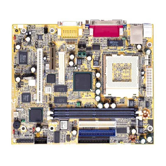
Page 12: 6Wfz7 Series Motherboard Layout
6WFZ7 Series Motherboard 6WFZ7 Series Motherboard Layout PS/2 JP21 JP26 TV-DFP JP23 JP11 AC97 PCISLOT1 6WFZ7 Front Phone+MIC JP18 ATX Power JP20 PGA 370 GMCH/GMCH-E 82810DC100 82559 JP12 JP16 AU8810 JP25 JP24 BIOS JP22 JP14 82801 JP15 JP17... -
Page 13: Page Index For Cpu Speed Setup / Connectors / Panel And Jumper Definition
Page Index for CPU Speed Setup / Connectors / Panel and Jumper Definition CPU Speed Setup Connectors COMA / VGA / LPT Port Game & Audio Port LAN & USB Connector TV/DFP PS/2 Keyboard & PS/2 Mouse Connector CPU Cooling FAN Power Connector Power Cooling FAN Power Connector System Cooling FAN Power Connector ATX Power... - Page 14 6WFZ7 Series Motherboard JP20 (STR Function Selection) P.25...
- Page 15 JP26 (LAN LED) [Optional] JP24 (FWH Write Protection) JP22 (Front USB Device Wake up Function) JP23 (Onboard LAN Wake up Function) [Optional] BAT 1 6WFZ7 Series Motherboard Layout P.26 P.26 P.27 P.27 P.28...
-
Page 17: Cpu Speed Setup
CPU Speed Setup The system bus frequency can be switched at 66MHz, 100MHz, 133MHz and Auto by adjusting JP3/JP25 (See Figure-1). The CPU Frequency is control by BIOS. The CPU speed must match with the frequency RATIO. It will cause system hanging up if the frequency RATIO is higher than that of CPU. -
Page 18: Connectors
6WFZ7 Series Motherboard Connectors COM A / VGA / LPT Port LPT PORT COM A Game & Audio Port GAME Port Line Out MIC In Line In... -
Page 19: Lan & Usb Connector
LAN & USB Connector TV/DFP : TV-Out / Digital Flat Panel Daughter card connector. Pin No. Definition 1 2 3 4 1 – Green LED (LAN Link LED) 2 Yellow LED (LAN Active LED) RED LINE Connectors USB V0 USB D0- USB D0+ USB V1 USB D1-... -
Page 20: Ps/2 Keyboard & Ps/2 Mouse Connector
6WFZ7 Series Motherboard PS/2 Keyboard & PS/2 Mouse Connector CPU Cooling FAN Power Connector PS/2 Mouse PS/2 Mouse/ Keyboard Pin No. PS/2 Keyboard Pin No. Definition +12V SENSE Definition Data VCC(+5V) Clock... -
Page 21: Power Cooling Fan Power Connector
Power Cooling FAN Power Connector System Cooling FAN Power Connector Pin No. Definition +12V SENSE Pin No. Definition +12V SENSE Connectors... -
Page 22: Atx Power
6WFZ7 Series Motherboard ATX Power Floppy Port Pin No. Definition 3,5,7,13,15-17 1,2,11 3.3V 4,6,19,20 +12V -12V Power Good 5V SB stand by+5V PS-ON(Soft On/Off) RED LINE... -
Page 23: Ide 1(Primary)/ Ide 2(Secondary) Port
IDE1(Primary) , IDE2 (Secondary) Port USB Port RED LINE IDE 2 IDE 1 Pin No. Definition USB V0 USB D0- USB D0+ USB V1 USB D1- USB D1+ Connectors... -
Page 24: Front Phone+Mic
6WFZ7 Series Motherboard Front Phone+MIC Pin No. Definition SPK_R SPK_L MIC-REF Pin No. Definition VCC(+5V) IR Data Input IR Data Output... -
Page 25: J7(Cd Audio Line In)
J7 : CD Audio Line In JP4 : TEL (The connector is for modem with internal voice connector) Pin No. Definition CD-L CD-R Pin No. Definition Signal-In Signal-Out Connectors... -
Page 26: Jp7(Aux In)
6WFZ7 Series Motherboard JP7 : AUX IN J10 : Ring Power On (Internal Modem Card Wake Up) Pin No. Definition AUX-L AUX-R Pin No. Definition Signal... -
Page 27: Jp15 (Str Led Connector & Dimm Led)
JP15 : STR LED Connector & DIMM LED JP11 : SPDIF(The SPDIF output is capable of providing digital audio to external speakers or compressed AC3 data to an external Dobly digital decoder.) (Optional) STR LED Connector External DIMM LED Pin No. Definition SPDIF OUT Connectors... -
Page 28: Panel And Jumper Definition
6WFZ7 Series Motherboard Panel and Jumper Definition J11 : For 2X11 Pins Jumper GN (Green Switch) GD (Green LED) HD (IDE Hard Disk Active LED) SPK (Speaker Connector) RE (Reset Switch) P+P P (Power LED) PW (Soft Power Connector) Open: Normal Operation Close: Entering Green Mode Pin 1: LED anode(+) Pin 2: LED cathode( ) -
Page 29: Jp21 (Rear Usb Device Wake Up Selection)
JP21 : Rear USB Device Wake up Selection (USB Connector à CN2) (If you want to use “ USB KB/Mouse Wake from S3 ” function, you have to set the BIOS setting “USB KB/Mouse Wake from S3” enabled, and the jumper “ JP21 ” enabled). *(Power on the computer and as soon as memory counting starts, press <Del>. -
Page 30: Jp6 (Top Block Lock)
6WFZ7 Series Motherboard JP6 : Top Block Lock JP9 : Onboard Sound Function Selection (Optional) Pin No. Definition Open Top Block Lock Close Top Block Unlock (Default) Pin No. Definition 1-2 close Onboard Sound Enable(Default) 2-3 close Onboard Sound Disable... -
Page 31: Jp8 (Amr Selection)
JP8 : AMR Selection JP12 : Onboard LAN Function (Optional) Panel and Jumper Definition Pin No. Definition 1-2close AMR Secondary AC’ 9 7 Disabled (Default) 2-3close (Disabled Onboard CODEC) Pin No. Definition 1-2 close Onboard LAN Disabled Onboard LAN Enabled 2-3 close (Default) -
Page 32: Jp14 (Timeout Reboot Function)
6WFZ7 Series Motherboard JP14 : Timeout Reboot Function JP16 : Case Open Pin No. Definition Open Timeout Reboot Close No Reboot on Timeout (Default) Pin No. Definition Signal... -
Page 33: Jp17 (Safe Mode/Recovery/Normal)
JP17 : Safe mode/Recovery/Normal JP18 : Clear CMOS Function Panel and Jumper Definition Pin No. Definition 1-2close Normal(Default) 2-3close Safe mode 1-2-3open Recovery Pin No. Definition 1-2 close Clear CMOS 2-3 close Normal (Default) -
Page 34: J13(Buzzer Enable)[Optional]
6WFZ7 Series Motherboard J13 : Buzzer Enable (Optional) JP20 : STR Function Selection Pin No. Definition Open Internal Buzzer Disabled Internal Buzzer Enabled Close (Default) Pin No. Definition Open STR Disabled(Default) Close STR Enabled... -
Page 35: Jp26 : Lan Led(Optional)
JP26 : LAN LED(Optional) JP24 : FWH Write Protection Panel and Jumper Definition Pin No. Definition Single Pin No. Definition Close Write Protection Open Normal (Default) -
Page 36: Jp22 (Front Usb Device Wake Up Function)
6WFZ7 Series Motherboard JP22 : Front USB Device Wake up Function (USB Port à J9) (If you want to use “ USB KB/Mouse Wake from S3 ” function, you have to set the BIOS setting “USB KB/Mouse Wake from S3” enabled, and the jumper “ JP22 ” enabled). *(Power on the computer and as soon as memory counting starts, press <Del>. -
Page 37: Bat
Panel and Jumper Definition BAT1 : Battery + Danger of explosion if battery is incorrectly replaced. + Replace only with the same or equivalent type recommended by the manufacturer. + Dispose of used batteries according to the manufacturer’ s instructions. -
Page 38: Performance List
6WFZ7 Series Motherboard Performance List The following performance data list is the testing results of some popular benchmark testing programs. These data are just referred by users, and there is no responsibility for different testing data values gotten by users. (The different Hardware & Software configuration will result in different benchmark testing results.) Intel Celeron DRAM... -
Page 39: Block Diagram
Block Diagram Display Display Cache ATA66 IDE Channels 4 USB Ports COM Port Winbond LPT Ports W83627 PS/2 Socket 370 66/100/133 MHz Host Bus 66/100/133MHz 66/100/133 MHz GMCH 82810/ 82810DC100/ 82810E 14.318/33/48/66 MHz Interface PCI Bus 33MHz 82801AA AC’ 97 Link AC’... -
Page 40: Suspend Ram Installation
6WFZ7 Series Motherboard Suspend to RAM Installation A.1 Introduce STR function: Suspend-to-RAM (STR) is a Windows 98 ACPI sleep mode function. When recovering from STR (S3) sleep mode, the system is able, in just a few seconds, to retrieve the last “state” of the system before it went to sleep and recover to that state. - Page 41 Step 2 : (If you want to use STR Function, please set jumper JP20 Closed.) Step 3: Power on the computer and as soon as memory counting starts, press <Del>. You will enter BIOS Setup. Select the item “POWER MANAGEMENT SETUP”, then select “ACPI Suspend Type: S3 (Suspend to RAM)”.
- Page 42 6WFZ7 Series Motherboard A.3 How to put your system into STR mode? There are two ways to accomplish this: 1. Choose the “Stand by” item in the “Shut Down Windows” area. A. Press the “Start” button and then select “Shut Down” B.
- Page 43 Suspend to RAM Installation Define the system ”power on” button to initiate STR sleep mode: A. Double click “My Computer” and then “Control Panel” B. Double click the “ Power Management” item.
- Page 44 6WFZ7 Series Motherboard C. Select the “Advanced” tab and “Standby” mode in Power Buttons. Step 4: Restart your computer to complete setup. Now when you want to enter STR sleep mode, just momentarily press the “Power on” button.. A.4 How to recover from the STR sleep mode? There are seven ways to “wake up”...
- Page 45 A.5 Notices : In order for STR to function properly, several hardware and software requirements must be satisfied: A. Your ATX power supply must comply with the ATX 2.01 specification (provide more than 720 mA 5V Stand-By current). B. Your SDRAM must be PC-100 compliant. Connector JP15 is provided to connect to the STR LED in your system chassis.
-
Page 46: Memory Installation
6WFZ7 Series Motherboard Memory Installation The motherboard has 2 dual inline memory module (DIMM) sockets. The BIOS will automatically detects memory type and size. To install the memory module, just push it vertically into the DIMM Slot .The DIMM module can only fit in one direction due to the two notch. Memory size can vary between sockets. -
Page 47: Page Index For Bios Setup
$ Page Index for BIOS Setup The Main Menu Standard CMOS Features Advanced BIOS Features Advanced Chipset Features Integrated Peripherals Power Management Setup PnP/ PCI Configuration PC Health Status Frequency / Voltage Control Load Fail-Safe Defaults Load Optimized Defaults Set Supervisor / User Password SAVE to CMOS and EXIT EXIT Without Saving BIOS Setup... -
Page 48: Entering Setup
6WFZ7 Series Motherboard BIOS Setup BIOS Setup is an overview of the BIOS Setup Program. The program that allows users to modify the basic system configuration. This type of information is stored in battery-backed CMOS RAM so that it retains the Setup information when the power is turned off. ENTERING SETUP Power ON the computer and press <Del>... -
Page 49: The Main Menu
GETTING HELP Main Menu The on-line description of the highlighted setup function is displayed at the bottom of the screen. Status Page Setup Menu / Option Page Setup Menu Press F1 to pop up a small help window that describes the appropriate keys to use and the possible selections for the highlighted item. - Page 50 6WFZ7 Series Motherboard Standard CMOS Features This setup page includes all the items in standard compatible BIOS. Advanced BIOS Features This setup page includes all the items of Award special enhanced features. Advanced Chipset Features This setup page includes all the items of chipset special features. Integrated Peripherals This setup page includes all onboard peripherals.
- Page 51 BIOS Setup Save & Exit Setup Save CMOS value settings to CMOS and exit setup. Exit Without Saving Abandon all CMOS value changes and exit setup.
-
Page 52: Standard Cmos Features
6WFZ7 Series Motherboard Standard CMOS Features The items in Standard CMOS Setup Menu (Figure 3) are divided into 9 categories. Each category includes no, one or more than one setup items. Use the arrows to highlight the item and then use the <PgUp>... - Page 53 Time The times format in <hour> <minute> <second>. The time is calculated base on the 24-hour military-time clock. For example, 1 p.m. is 13:00:00. IDE Primary Master, Slave / Secondary Master, Slave The category identifies the types of hard disk from drive C to F that has been installed in the computer.
- Page 54 6WFZ7 Series Motherboard Floppy 3 Mode Support (for Japan Area) Disabled Normal Floppy Drive. Drive A Drive A is 3 mode Floppy Drive. Drive B Drive B is 3 mode Floppy Drive. Both Drive A & B are 3 mode Floppy Drives. Video The category detects the type of adapter used for the primary system monitor that must match your video display card and monitor.
-
Page 55: Base Memory
Memory The category is display-only which is determined by POST (Power On Self Test) of the BIOS. Base Memory The POST of the BIOS will determine the amount of base (or conventional) memory installed in the system. The value of the base memory is typically 512 K for systems with 512 K memory installed on the motherboard, or 640 K for systems with 640 K or more memory installed on the motherboard. -
Page 56: Advanced Bios Features
6WFZ7 Series Motherboard Advanced BIOS Features CMOS Setup Utility-Copyright( C ) 1984-1999 Award Software Virus Warning CPU Cache CPU L2 Cache ECC Checking Processor Number Feature Quick Power On Self Test First Boot Device Second Boot Device Third Boot Device Boot Other Device Swap Floppy Drive Boot Up Floppy Seek... -
Page 57: Processor Number Feature
CPU Cache These two categories speed up memory access. However, it depends on CPU / chipset design. Enable cache. ( Default value ) Enabled Disabled Disable cache. CPU L2 Cache ECC Checking Enabled Enable CPU L2 Cache ECC Checking. Disabled Disable CPU L2 Cache ECC Checking. - Page 58 6WFZ7 Series Motherboard Swap Floppy Drive Enabled Floppy A & B will be swapped under DOS. Floppy A & B will be normal definition. ( Default value ) Disabled Boot Up Floppy Seek During POST, BIOS will determine the floppy disk drive installed is 40 or 80 tracks. 360 K type is 40 tracks 720 K, 1.2 M and 1.44 M are all 80 tracks.
- Page 59 BIOS Setup...
-
Page 60: Security Option
6WFZ7 Series Motherboard Security Option This category allows you to limit access to the system and Setup, or just to Setup. System The system can not boot and can not access to Setup page will be denied if the correct password is not entered at the prompt. Setup The system will boot, but access to Setup will be denied if the correct password is not entered at the prompt. -
Page 61: Advanced Chipset Features
Advanced Chipset Features CMOS Setup Utility-Copyright( C ) 1984-1999 Award Software Advanced Chipset Features SDRAM CAS Latency Time SDRAM Cycle Time Tras/Trc SDRAM RAS-to-CAS Delay SDRAM RAS Precharge Time SDRAM Buffer Strength DRAM Page Closing Policy System BIOS Cacheable Video BIOS Cacheable Delayed Transaction On-Chip Video Window Size Local Memory Frequency... - Page 62 6WFZ7 Series Motherboard SDRAM RAS Precharge Set SDRAM RAS Precharge is 3. Set SDRAM RAS Precharge is 2. ( Default value ) SDRAM Buffer Strength Set SDRAM Buffer Strength is Auto. ( Default Value ) Auto Auto+1 Set SDRAM Buffer Strength is Auto+1. Auto-1 Set SDRAM Buffer Strength is Auto-1.
-
Page 63: Integrated Peripherals
Display Cache Timing Auto Set Display Cache Timing to Auto. ( Default value ) Fast Set Display Cache Timing to Fast. Normal Set Display Cache Timing to Normal. Integrated Peripherals CMOS Setup Utility-Copyright( C ) 1984-1999 Award Software On-Chip Primary PCI IDE On-Chip Secondary PCI IDE IDE Primary Master PIO IDE Primary Slave PIO... - Page 64 6WFZ7 Series Motherboard On-Chip Primary PCI IDE Enabled Enable onboard 1st channel IDE port. ( Default value ) Disabled Disable onboard 1st channel IDE port. On-Chip Secondary PCI IDE Enable onboard 2nd channel IDE port. ( Default value ) Enabled Disabled Disable onboard 2nd channel IDE port.
- Page 65 IDE Secondary Master UDMA Auto BIOS will automatically detect the IDE HDD Accessing mode. ( Default value ) Disabled Disable UDMA function. IDE Secondary Slave UDMA Auto BIOS will automatically detect the IDE HDD Accessing mode. ( Default value ) Disabled Disable UDMA function.
-
Page 66: Onboard Fdc Controller
6WFZ7 Series Motherboard POWER ON Function Password Enter from 1 to 5 characters to set the Keyboard Power On Password. Mouse Left Double click twice on PS/2 left bottom. Mouse Right Double click twice on PS/2 right bottom. BUTTON ONLY If your keyboard have “POWER Key”... -
Page 67: Onboard Parallel Port
Onboard Parallel port 378/IRQ7 Enable onboard LPT port and address is 378/IRQ7. ( Default value ) 278/IRQ5 Enable onboard LPT port and address is 278/IRQ5. Disabled Disable onboard LPT port. 3BC/IRQ7 Enable onboard LPT port and address is 3BC/IRQ7. Parallel Port Mode Using Parallel port as Standard Parallel Port. -
Page 68: Power Management Setup
6WFZ7 Series Motherboard Power Management Setup CMOS Setup Utility-Copyright( C ) 1984-1999 Award Software Power Management Setup ACPI Suspend Type Power Management Video Off Method Video Off In Suspend Suspend Type MODEM Use IRQ Suspend Mode HDD Power Down Soft-Off by PWR-BTTN Power LED in Suspend AC BACK Function Wake-Up by PCI card... -
Page 69: Power Management
ACPI Suspend Type S1(PowerOn Suspend) Set ACPI Suspend type is S1. ( Default value ) S3(Suspend to RAM) Set ACPI Suspend type is S3. Power Management User Define For configuring our own power management features. ( Default value ) Min Saving Enable Green function. - Page 70 6WFZ7 Series Motherboard Suspend Mode Disabled Disable Suspend Mode. ( Default value ) 1 min - 1 Hour Setup the timer to enter Suspend Mode. HDD Power Down Disable HDD Power Down mode function. ( Default value ) Disable 1-15 mins. Enable HDD Power Down mode between 1 to 15 mins.
- Page 71 USB KB/Mouse Wake From S3 Disabled Disabled this function. ( Default value ) Enabled Enabled USB KB/Mouse Wake From S3 function. CPU Thermal-Throttling 87.5% Monitor CPU Temp. will cause system slow down CPU Duty Cycle to 87.5%. 75.0% Monitor CPU Temp. will cause system slow down CPU Duty Cycle to 75.0%.
-
Page 72: Pnp/ Pci Configuration
6WFZ7 Series Motherboard FDD/COM/LPT Port Disabled Disable this function. Enabled Enable monitor FDC/COM/LPT for Green event. ( Default value ) PCI PIRQ[A-D] # Enabled Monitor PCI PIRQ[A-D] IRQ Active. ( Default value ) Disabled Ignore PCI PIRQ[A-D] IRQ Active. PnP/PCI Configurations CMOS Setup Utility-Copyright( C ) 1984-1999 Award Software PNP OS Installed Reset Configuration Data... -
Page 73: Reset Configuration Data
Reset Configuration Data Disabled Disable this function. ( Default value ) ESCD Clear PnP information in ESCD. Update Desktop Management Information data. Both Clear PnP information in ESCD & update DMI data. Resources Controlled by Manual User can set the PnP resource (I/O Address, IRQ & DMA channels) used by legacy ISA DEVICE. -
Page 74: Pc Health Status
6WFZ7 Series Motherboard PC Health Status CMOS Setup Utility-Copyright( C ) 1984-1999 Award Software Reset Case Open Status Case Opened Current CPU Temperature CPU FAN Speed Power FAN Speed System FAN speed VCORE VGTL VCC3 + 5V +12V - 12V - 5V VBAT 5VSB... - Page 75 CPU FAN / Power FAN / System FAN Speed (RPM) Detect Fan speed status automatically. Current Voltage (V) VCORE / VGTL/ VCC3 / 12V / 5V / 5VSB / VBAT Detect system’s voltage status automatically. CPU Warning Temperature ( C / F) 65 C / 149 F Monitor CPU Temp.
-
Page 76: Frequency/Voltage Control
6WFZ7 Series Motherboard Frequency/Voltage Control CMOS Setup Utility-Copyright( C ) 1984-1999 Award Software Frequency/Voltage Control Auto Detect DIMM/PCI Clk Spread Spectrum CPU Type INTEL(R) CELERON Move Enter:Select +/-/PU/PD:Value F10:Save ESC:Exit F5:Previous Values F6:Fail-Safe Defaults F7:Optimized Defaults Figure 10: Frequency/Voltage Control Auto Detect DIMM/PCI Clk Disabled Disabled Auto Detect DIMM/PCI Clk. -
Page 77: Load Fail-Safe Defaults
Load Fail-Safe Defaults CMOS Setup Utility-Copyright( C ) 1984-1999 Award Software 4 Standard CMOS Features 4Advanced BIOS Features 4Advanced Chipset Features 4Integrated Peripherals 4Power Management Setup 4PnP/PCI Configurations Load Fail-Safe Defaults (Y/N)? N 4PC Health Status ESC:Quit F10:Save & Exit Setup Figure 11: Load Fail-Safe Defaults Load Fail-Safe Defaults Fail Safe defaults contain the most appropriate values of the system parameters that allow... -
Page 78: Load Optimized Defaults
6WFZ7 Series Motherboard Load Optimized Defaults CMOS Setup Utility-Copyright( C ) 1984-1999 Award Software 4 Standard CMOS Features 4Advanced BIOS Features 4Advanced Chipset Features 4Integrated Peripherals 4Power Management Setup 4PnP/PCI Configurations Load Optimized Defaults (Y/N)? N 4PC Health Status ESC:Quit F10:Save &... -
Page 79: Set Supervisor / User Password
Set Supervisor / User Password When you select this function, the following message will appear at the center of the screen to assist you in creating a password. CMOS Setup Utility-Copyright( C ) 1984-1999 Award Software 4 Standard CMOS Features 4Advanced BIOS Features 4Advanced Chipset Features 4Integrated Peripherals... -
Page 80: Save To Cmos And Exit
6WFZ7 Series Motherboard Save & Exit Setup CMOS Setup Utility-Copyright( C ) 1984-1999 Award Software 4 Standard CMOS Features 4Advanced BIOS Features 4Advanced Chipset Features 4Integrated Peripherals 4Power Management Setup 4PnP/PCI Configurations SAVE to CMOS and EXIT (Y/N)? Y 4PC Health Status ESC:Quit F10:Save &... -
Page 81: Exit Without Saving
Exit Without Saving CMOS Setup Utility-Copyright( C ) 1984-1999 Award Software 4 Standard CMOS Features 4Advanced BIOS Features 4Advanced Chipset Features 4Integrated Peripherals 4Power Management Setup 4PnP/PCI Configurations Quit Without Saving (Y/N)? N 4PC Health Status ESC:Quit F10:Save & Exit Setup Type "Y"... -
Page 83: Appendix
Appendix Appendix A : Onboard Driver Installation Procedure (In this manual, we assume that your CD-ROM Drive letter to be Drive D: ) Please reference IUCD CD directory D: \ Manual \ Whitney 810.pdf Appendix B : 810 INF update utility can’t find ICHxIDE.cat file automatically After the installation is of Winodws98 is completed, run the “Setup.exe”... - Page 84 6WFZ7 Series Motherboard Appendix C : AU8810 Driver Installation A. DRIVER INSTALLATION If you have older drivers in your system, please uninstall them first as described in Section C below. 1. Power on the system, placing the "Intel chipset Series Mainboard Utility CD" in the CD-ROM drive.
- Page 85 2. Open the "Multifunction Adapters" tree and select "Vortex Multifunction PCI Platform" 3. Press the "Remove" button at the bottom of the Device Manager window pane. 4. The drivers are now removed from memory, but are still on the hard disk. To delete the files from the hard disk: a.
- Page 86 C:\utility\ AWDFlash or AMIFlash <filename of the BIOS binary file intended for flashing> Once the process is finished, reboot the system ü MNote: Please download the newest BIOS from our website (www.gigabyte.com.tw) or contact your local dealer for the file.
- Page 87 Appendix E : Acronyms Acor. Meaning ACPI Advanced configuration and power interface POST Power-on self test Local area network Extended capabilities port Advanced power management Direct memory access Megahertz ESCD Extended system configuration data Central processing unit Symmetric multi-processing Universal serial bus Operating System Error checking and correcting Integrated dual channel enhanced...
- Page 88 6WFZ7 Series Motherboard Acor. Meaning Peripheral component interconnect RIMM Rambus In-line Memory Module Dual retention mechanism Industry standard architecture CRIMM Continuity RIMM...
Need help?
Do you have a question about the GA-6WFZ7 and is the answer not in the manual?
Questions and answers