Table of Contents
Advertisement
Quick Links
EVK-M8GZOE
Evaluation Kit
User Guide
Abstract
This document describes the structure and use of the EVK-M8GZOE evaluation kit and provides
information for evaluating and testing the u-blox ZOE-M8G GNSS module. EVK-M8GZOE is also
suitable to evaluate the GNSS performance of ZOE-M8Q module.
www.u-blox.com
UBX-16030132 - R04
Advertisement
Table of Contents

Related Manuals for Ublox EVK-M8GZOE


Summary of Contents for Ublox EVK-M8GZOE
- Page 1 Evaluation Kit User Guide Abstract This document describes the structure and use of the EVK-M8GZOE evaluation kit and provides information for evaluating and testing the u-blox ZOE-M8G GNSS module. EVK-M8GZOE is also suitable to evaluate the GNSS performance of ZOE-M8Q module.
-
Page 2: Document Information
Document contains the final product specification. End of Life European Union regulatory compliance EVK-M8GZOE complies with all relevant requirements for RED 2014/53/EU. The EVK-M8GZOE Declaration of Conformity (DoC) is available at www.u-blox.com within Support --> Product Resources --> Conformity Declaration. -
Page 3: Table Of Contents
EVK-M8GZOE - User Guide Contents Document Information ..........................2 Contents ................................3 Product description ..........................5 1.1 Overview ................................ 5 Evaluation kit versions ........................5 Features ..............................5 1.2 Kit includes ..............................5 1.3 Software and documentation ........................5 1.4 u-center GNSS evaluation software ......................6 1.5 System requirements .......................... - Page 4 EVK-M8GZOE - User Guide 5.2 Measurement with an external current measuring power supply ..........19 Testing Power Save Mode ....................... 20 Board assembly ........................... 21 Schematic ............................. 24 Troubleshooting ..........................26 10 Common evaluation pitfalls ......................28 Related documents ........................... 29 Revision history ............................
-
Page 5: Product Description
• Active GNSS antenna with a 3 m cable • USB cable ☞ A plastic cap is attached on the top of the GNSS S-LGA Module in EVK-M8GZOE. The purpose of the cap is to prevent air flow at ZOE-M8G. 1.3 Software and documentation The EVK-M8GZOE installation software and documentation can be downloaded from the Web. -
Page 6: U-Center Gnss Evaluation Software
EVK-M8GZOE User Guide EVK-M8GZOE Quick Start Guide [5] is available from http://start.u-blox.com. u-center GNSS evaluation software and Windows driver for the evaluation board are available from web. See section 3.1 for details. 1.4 u-center GNSS evaluation software The installation software includes u-center, which is an interactive tool for configuration, testing, visualization and data analysis of GNSS receivers. -
Page 7: Specifications
Table 2: EVK-M8GZOE specification 2.1 Safety precautions EVK-M8GZOE must be supplied by an external limited power source in compliance with the clause 2.5 of the standard IEC 60950-1. In addition to external limited power source, only Separated or Safety Extra-Low Voltage (SELV) circuits are to be connected to the evalkit including interfaces and antennas. -
Page 8: Getting Started
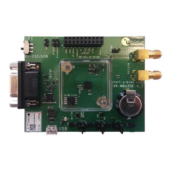
Make sure you select the driver version that does not include “Serial Enumeration” functionality. 3.2 Hardware installation This section describes the evaluation board connectors and configuration settings that are required to get started. Figure 1 shows an overview of EVK-M8GZOE board and its connectors. Figure 1: Getting started overview UBX-16030132 - R04... -
Page 9: Interface Default Configuration
EVK-M8GZOE User Guide 1. Make sure the “Interface Switch” is at RS-232 / USB side (and not SPI side). 2. Connect the jumpers J4, J7 and J6 as above. 3. Connect the evaluation board to a PC by micro USB cable and / or RS-232. -
Page 10: Device Description
5V main power supply The EVK-M8GZOE board must be supplied either by the micro USB connector or by an external 4.5 V – 5.5 V power supply connected to digital connector pin 2 and GND to pin 18. See Figure 1. -
Page 11: Interface Switch
M8GZOE there is a USB to UART converter to the UART interface of ZOE-M8G. The easiest way to evaluate the EVK-M8GZOE operation is to connect the board to a PC by a micro USB cable and then to use u-center to configure and monitor the GNSS function. -
Page 12: Uart
The digital connector J1 contains pins for evaluating DDC (I²C) bus communication. For such evaluation the interface switch must be in correct position: RS-232 / USB. Additional pull-ups on DDC lines to 1.8 V can be installed on the EVK-M8GZOE if needed, see R4 and R6 in Figure 10. -
Page 13: Active Antenna Input
Do not use both GNSS inputs at the same time. Either use the passive (simulator) or use the active antenna input. Figure 3: EVK-M8GZOE schematic of GNSS inputs There is a RF switch (U14) which only allows one of the 2 GNSS signal inputs to ZOE-M8G. -
Page 14: Digital Connector
4.5 LED On the EVK-M8GZOE, the blue LED shows the time pulse 1 signal. The LED starts flashing with one pulse per second if doing GNSS fixes. If there is no GNSS fix, the LED will only light, without flashing. -
Page 15: Reset_N And Safeboot_N
RESET_N and SAFEBOOT_N are available on jumpers (J5 and J10) as well as on digital connector J1. See section 4.4 for more information. 4.8 EXTINT On the EVK-M8GZOE, the EXTINT signal of ZOE-M8G is available on digital connector J1 (see section 4.4), and on RS-232 connector (see section 4.2.3). ☞... -
Page 16: Measuring Current Consumption (Zoe-M8G Only)
Figure 4: EVK-M8GZOE board measuring the ZOE-M8G VCC current On the EVK-M8GZOE there is a 1.8 V LDO supplying the ZOE-M8G main supply (VCC). At the input of that LDO is a 1 Ω current measurement shunt resistor placed in between J7 pin 1 and pin 2, see Figure 4. -
Page 17: Zoe-M8G Vcc Current
EVK-M8GZOE User Guide ZOE-M8G VCC current To measure the acquisition and tracking power consumption with the EVK-M8GZOE, follow the below steps, a picture of the setup can be seen at Figure 5: 1. Connect a voltmeter to J7 pin 1 and pin 2 to see the voltage over the 1 Ω current measurement shunt resistor in the VCC supply. -
Page 18: Zoe-M8G V_Bckp Current
3. Read the voltage on the voltmeter and convert to current. 1 mV equals 10 uA. Figure 6: Setup to measure the V_BCKP current consumption of ZOE-M8G on EVK-M8GZOE See Figure 6 for an example where 0.0016V is measured by multimeter over 100 Ω V_BCKP shunt resistor. -
Page 19: Measurement With An External Current Measuring Power Supply
EVK-M8GZOE User Guide 5.2 Measurement with external current measuring power supply For customers using their own current measurement setup, the current consumption of VCC and V_BCKP of ZOE-M8G can also be measured with an external current measuring power supply. Figure 7: Measuring power consumption with external power supply In Figure 7, the VCC and V_BCKP power supply circuitry have been disconnected from the main power supply and Gold Capacitor (J6 and J7 removed). -
Page 20: Testing Power Save Mode
EVK-M8GZOE User Guide Testing Power Save Mode When testing Power Save Mode with EVK-M8GZOE, observe the following points: • A set of predefined power mode setups can be selected using the CFG-PMS message. The Configuration view or Messages view of the u-center evaluation software can be used to do this. -
Page 21: Board Assembly
EVK-M8GZOE User Guide Board assembly Figure 8 shows the EVK-M8GZOE assembly. See Table 6 for the component list. Figure 8: EVK-M8GZOE assembly UBX-16030132 - R04 Board assembly Page 21 of 30 Early Production Information... - Page 22 EVK-M8GZOE User Guide Part Description C1 C3 C4 C6 C9 C18 C20 C21 CAP CER X5R 0402 TY 1U0 10% 6.3V C22 C23 C26 C27 C34 C35 C37 C2 C16 C31 C33 CAP CER X7R 0402 100N 10% 16V -55/+125C...
- Page 23 EVK-M8GZOE User Guide Part Description 2 WAY SUB-MINIATURE SLIDE SWITCH SMD JS SERIES - SPDT -40/+85C U1 U7 LOW DROPOUT REGULATOR ON SEMI NCV8705 WDFN6 0.5A 1.8V PRECISION RAIL TO RAIL OP AMP LINEAR LT6000 DCB GNSS RECEIVER U-BLOX ZOE-M8G S-LGA51 -40/+85C U5 U11 U17 TINY LOGIC ULP-A 2-INPUT AND GATE 1.45X1.0 6-LEAD MICROPAK -40/+85C...
-
Page 24: Schematic
EVK-M8GZOE User Guide 8 Schematic Figure 9: Schematic EVK-M8GZOE Version E, page 1 of 2: DNI=TRUE in the schematic means: Component not installed UBX-16030132 - R04 Schematic Page 24 of 30... - Page 25 EVK-M8GZOE User Guide Figure 10: Schematic EVK-M8GZOE Version E, page 2 of 2: DNI=TRUE in the schematic means: Component not installed UBX-16030132 - R04 Schematic Page 25 of 30...
-
Page 26: Troubleshooting
If a COM Port is gray, another application running on this computer is using it. After installing USB driver for the first time by connecting EVK-M8GZOE to PC with USB cable, the cursor on PC starts to jump around the screen This behavior is caused when the NMEA 0183 GNSS serial data is misinterpreted as mouse data by the serial port enumerator (serenum.sys), resulting in erratic mouse cursor activity. - Page 27 40 dBHz to about 50 dBHz. With a standard off-the-shelf active antenna, 47 dBHz should easily be achieved. Low C/No values lead to a prolonged startup time. The EVK-M8GZOE does not work properly when connected with a GNSS simulator There is RF-input for simulator signal (passive).
-
Page 28: Common Evaluation Pitfalls
EVK-M8GZOE User Guide 10 Common evaluation pitfalls • Parameter may have the same name but a different definition. GNSS receivers may have a similar size, price and power consumption but can still have different functionalities (e.g. no support for passive antennas, different temperature range). Also, the definitions of hot, warm, cold start times may differ between suppliers. -
Page 29: Related Documents
EVK-M8GZOE User Guide Related documents ZOE-M8 Data Sheet, Doc. No. UBX-16008094 ZOE-M8 Hardware Integration Manual, Doc. No.UBX-16030136 u-blox 8 / u-blox M8 Receiver Description including Protocol Specification, Doc. No. UBX-13003221 (Public Release) u-center User Guide, Doc. No. UBX-13005250 Quick Start Guide, Doc, No. UBX-17013022 Information technology equipment –... -
Page 30: Contact
EVK-M8GZOE User Guide Contact For complete contact information, visit us at www.u-blox.com. u-blox Offices North, Central and South America Headquarters Asia, Australia, Pacific Europe, Middle East, Africa u-blox America, Inc. u-blox Singapore Pte. Ltd. u-blox AG Phone: +1 703 483 3180...
Need help?
Do you have a question about the EVK-M8GZOE and is the answer not in the manual?
Questions and answers