
Related Manuals for ANTAIRA LNP-0800-T


Summary of Contents for ANTAIRA LNP-0800-T
- Page 1 LNP-0800 series 8-port Industrial PoE+ Unmanaged Ethernet Switches 8*10/100Tx (30W/Port) User Manual...
- Page 2 FCC Warning This Equipment has been tested and found to comply with the limits for a Class-A digital device, pursuant to Part 15 of the FCC rules. These limits are designed to provide reasonable protection against harmful interference in a residential installation. This equipment generates, uses, and can radiate radio frequency energy.
-
Page 3: Table Of Contents
Content Introduction ..............1 Features ..............1 Package Contents ............ 2 Hardware Description ..........3 Physical Dimension ..........3 Front Panel .............. 4 Top View ..............4 LED Indicators ............5 Ports ................. 6 Cabling ..............7 Wiring the Power Inputs ........... 8 Wiring the Fault Alarm Contact ........ -
Page 4: Introduction
Introduction Antaira’s LNP-0800 series switches are smart 8-port Industrial Unmanaged Ethernet Switches supporting IEEE-802.3at compliant (Power-over-Ethernet Plus) on ports 1 to 8. The switches are classified as power source equipment (PSE), and when used in this way, the LNP-0800 series switches enable centralization of the power supply and provide up to 30 watts of power per port. -
Page 5: Package Contents
Removable Terminal Block Wall-mount Kit (2 Wall-mount Plates with Screws) Compare the contents of the industrial switch with the checklist above. If any item is damaged or missing, please contact Antaira or Antaira’s authorized channel partners for service. -
Page 6: Hardware Description
Hardware Description The Industrial switch’s hardware spec, port, cabling information, and wiring installation will be described. Physical Dimension The LNP-0800 series - 8-Port Industrial PoE+ Unmanaged Ethernet Switch dimension: (W x D x H) is 30mm x 99mm x 142mm... -
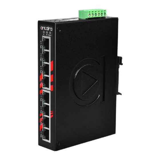
Page 7: Front Panel
Front Panel The Front Panel of the PoE Industrial Switch is shown below: Front Panel of the PoE Industrial Switch Top View The top view of the PoE Industrial Switch has one terminal block connector of two DC power inputs and relay circuit contact. One DIP switch for port break alarm mask and broadcast storm protection. -
Page 8: Led Indicators
LED Indicators The diagnostic LEDs located on the front panel of the industrial switch provide real-time information of the system and optional status. The following table provides the description of the LED status. Color Description Power input 1 is active Green Power input 1 is inactive Power input 2 is active... -
Page 9: Ports
Ports RJ-45 ports The (RJ-45) Fast Ethernet ports will auto-sense for 10Base-T or 100Base-TX connections. Auto MDI/MDIX means that the switch can connect to another switch or workstation without changing straight through or crossover cabling. Please refer to the table below for RJ-45 pin assignment. -
Page 10: Cabling
The following figures show the cable schematic for both straight-through type and crossover type. Straight Through Cable Schematic Cross Over Cable Schematic Cabling Twisted-pair segments can be connected with an unshielded twisted pair (UTP) or shielded twisted pair (STP) cable. The cable must comply with the IEEE 802.3u 100Base TX standard (e.g. -
Page 11: Wiring The Power Inputs
Wiring the Power Inputs Please follow the steps below to insert the power wire. Insert the positive and negative wires into the PWR1 (V1+, V1-) and PWR2 (V2+,V2-) contacts on the terminal block connector. Tighten the wire-clamp screws to prevent the wires from loosening. Note Use Copper Conductors Only, 60/75 °... -
Page 12: Wiring The Fault Alarm Contact
Wiring the Fault Alarm Contact The fault alarm contact is in the middle of the terminal block connector as the picture shows below. By Inserting the wires, it will detect the fault status including power failure or port link failure (managed industrial switch only) and form a normally open circuit. An application example for the fault alarm contact is shown as below: Note Use Copper Conductors Only, 60/75 °... -
Page 13: Mounting Installation
Mounting Installation DIN-Rail Mounting The DIN-Rail is screwed on the industrial switch from the factory. If the DIN-Rail is not screwed on the industrial switch, please see the following pictures to screw the DIN-Rail on the switch. Follow the steps below to hang the industrial switch. Use the screws to screw the DIN-Rail bracket on the rear side of the industrial switch. - Page 14 DIN-Rail on to the track. Then, lightly pull down the bracket on to the rail. Check if the bracket is mounted tight on the rail. To remove the industrial switch from the rail, reverse steps above.
-
Page 15: Wall Mounting
Wall Mounting Follow the steps below to mount the industrial switch using the wall mount bracket. 1. Remove the DIN-Rail bracket from the industrial switch; loosen the screws to remove the DIN-Rail. 2. Place the wall mount bracket on the top and bottom of the industrial switch. 3. -
Page 16: Hardware Installation
Hardware Installation This section is to explain how to install the LNP-0800 series Industrial PoE+ Unmanaged Ethernet Switch. Installation Steps 1. Unpack the Industrial switch packing. 2. Check if the DIN-Rail bracket is screwed on the Industrial switch. If the DIN-Rail is not screwed on the Industrial switch, please refer to the DIN-Rail Mounting section for DIN-Rail installation. -
Page 17: Network Application
Network Application This segment provides an example of an industrial switch application. -
Page 18: Troubleshooting
If the power indicator LED does not turn on when the power cord is plugged in, the user may have a problem with the power cord. Check for loose power connections, power losses or surges at the power outlet. Please contact Antaira or Antaira’s authorized channel partners for technical support service, if the problem still cannot be resolved. -
Page 19: Technical Specification
Technical Specification The LNP-0800 series - 8-Port Industrial PoE+ Unmanaged Ethernet Switch technical specifications is shown below. IEEE 802.3 10Base-T Ethernet IEEE 802.3u 100Base-TX Fast Ethernet Standard IEEE802.3x Flow Control and Back Pressure IEEE802.3at Power over Ethernet Protocol CSMA/CD 14,880 pps for 10Base-T Ethernet port Transfer Rate 148,800 pps for 100Base-TX Fast Ethernet port MAC Address... - Page 20 Max Power 210 Watts @ 48V, 250 Watts @ 51-55V Consumption Full Load with PoE Function Installation DIN Rail Mounting, Wall Mounting Standard Operating Temperature: -10 C to 70 Operating Temp. Wide Temperature model: -40 C to 75 Operating 5% to 95% (Non-Condensing) Humidity Storage C to 85...
Need help?
Do you have a question about the LNP-0800-T and is the answer not in the manual?
Questions and answers