Table of Contents
Advertisement
Quick Links
Advertisement
Table of Contents

Related Manuals for Advantech ARK-2250L-U6A1E


Summary of Contents for Advantech ARK-2250L-U6A1E
- Page 1 User Manual ARK-2250 Computer...
- Page 2 Attention! Please note: This package contains a hard-copy user manual in Chinese for China CCC certifica- tion purposes, and there is an English user manual included as a PDF file on the website. Please disregard the Chinese hard copy user manual if the product is not to be sold and/or installed in China.
- Page 3 The documentation and the software included with this product are copyrighted 2017 by Advantech Co., Ltd. All rights are reserved. Advantech Co., Ltd. reserves the right to make improvements in the products described in this manual at any time without notice.
- Page 4 Because of Advantech’s high quality-control standards and rigorous testing, most of our customers never need to use our repair service. If an Advantech product is defec- tive, it will be repaired or replaced at no charge during the warranty period. For out- of-warranty repairs, you will be billed according to the cost of replacement materials, service time and freight.
- Page 5 Technical Support and Assistance Visit the Advantech web site at www.advantech.com/support where you can find the latest information about the product. Contact your distributor, sales representative, or Advantech's customer service center for technical support if you need additional assistance. Please have the following information ready before you call: –...
- Page 6 Ordering Information Model Number Description ARK-2250L-U6A1E ARK-2250L Intel Core i7-6600U 2.6GHz system ARK-2250L-U3A1E ARK-2250L Intel Core i3-6100U 2.3GHz system Optional Accessories For ARK-2250 Part Number Description 96PSA-A60W12W6 AC-to-DC Adapter, DC12V/5A 60W with lockable DC jack MOS-1120Y-0201E Isolated RS-232, 2-Ch, DB9...
- Page 7 Safety Instructions Please read these safety instructions carefully. Please keep this User’s Manual for later reference. Please disconnect this equipment from AC outlet before cleaning. Use a damp cloth. Don’t use liquid or sprayed detergent for cleaning. Use moisture sheet or clothe for cleaning.
- Page 8 This equipment has been tested and found to comply with the limits for a Class B digital device, pursuant to Part 15 of the FCC Rules. These limits are designed to provide reasonable protection against harmful interference in a residential installation. ...
-
Page 9: Table Of Contents
Contents Chapter General Introduction ......1 Introduction ....................2 Product Features..................3 1.2.1 General ..................3 1.2.2 Display ..................3 1.2.3 Ethernet ..................3 Chipset ...................... 4 1.3.1 Functional Specification ..............4 1.3.2 WISE-PaSS/RMM................. 5 Mechanical Specifications................. 5 1.4.1 Dimensions ................... 5 Figure 1.1 ARK-2250 Mechanical dimension drawing.... - Page 10 2.4.3 mSATA Installation ..............39 2.4.4 Power Module (MIOe-PWR2) Installation (Option)..... 40 2.4.5 iDoor Module Installation (Option) ..........43 2.4.6 2nd Layer MIOe Module Installation (Option) ......43 Chapter BIOS Settings ........45 BIOS Setup ..................... 46 Figure 3.1 Setup program initial screen........46 Entering Setup ..................
-
Page 11: Chapter 1 General Introduction
Chapter General Introduction This chapter gives background information on ARK-2250 series. -
Page 12: Introduction
AVC/VC1/MPEG2 HW Decode. Built in Intelligent Management Tools - WISE-PaSS/RMM Advantech WISE-PaSS/RMM provides a valuable suite of programmable APIs such as multi-level watchdog, hardware monitor, system restore, and other user-friendly interface. iManager is an intelligent self-management cross platform tool that moni- tors system status for problems and takes action if anything is abnormal. -
Page 13: Product Features
Product Features 1.2.1 General CPU: Intel 6th gen core i7-6600U processor 2.6GHz Intel 6th gen core i3-6100U processor 2.3GHz BIOS: AMI UEFI 128Mbit System Memory: 1x DDR3L 1600MHz up to 16 GB Watchdog Timer: Single chip Watchdog 255-level interval timer, setup by soft- ... -
Page 14: Chipset
Chipset 1.3.1 Functional Specification 1.3.1.1 Processor Intel 6th gen core i7-6600U processor 2.6GHz Processor Intel 6th gen core i3-6100U processor 2.3GHz Supports DDR3L 1600MHz up to 16GB Memory 1 x 204-pin SODIMM socket type 1.3.1.2 Chipset DirectX 11.3, OpenGL 4.4 Internal Graph- ics Features ... -
Page 15: Wise-Pass/Rmm
1.3.2 WISE-PaSS/RMM Sequence control Supported Watchdog timer Multi Level WDT Programmable 1-255 sec / min Hardware monitor CPU Temperature / input Current / input Voltage Power saving Deep sleep S5 mode System information Running HR / Boot record Mechanical Specifications 1.4.1 Dimensions 260[10.24] x 54[2.13] x 140.2[5.52] Unit: mm [Inch]... -
Page 16: Environment Specification
Environment Specification 1.6.1 Operating Temperature With Industrial Grade SSD/mSATA: -20 ~ 60° C (-4~140° F), with air flow, speed=0.7 m/sec With 2.5-inch hard disk 0 to 45° C (32~113° F), with air flow, speed=0.7 m/sec 1.6.2 Relative Humidity ... -
Page 17: Chapter 2 H/W Installation
Chapter H/W Installation This chapter introduces external IO and the installation of ARK- 2250 hardware. -
Page 18: Introduction
Introduction The following sections show the internal jumpers settings and the external connector pin assignments for application. Jumpers 2.2.1 Jumper Description You may configure ARK-2250 to match the needs of your application by setting jump- ers. A jumper is a metal bridge used to close an electric circuit. It consists of two metal pins and a small metal clip (often protected by a plastic cover) that slides over the pins to connect them. -
Page 19: Jumper List
2.2.2 Jumper List Table 2.1: Jumper setting Auto Power On Setting RTC Reset 2.2.3 Jumper Location Figure 2.1 Jumper Layout 2.2.4 Jumper Setting On the Motherboard Auto Power On Setting Part Number 1653002101 Footprint HD_2x1P_79_D Description PIN HEADER 2*1P 180D(M)SQUARE 2.0mm DIP W/O Pb Setting Function Power On by power button (default) -
Page 20: Connectors
RTC Reset Part Number 1600000071 Footprint SW_3P_CJS-1201TA1 Description CJS-1201TA1 Setting Function Normal (Default) RTC Reset Connectors Table 2.2: Connectors 12V Power Input NL/DCJACK_2 Battery SODIMMDDR3_204 EC Debug Port Power Switch Reset CN10 GPIO CN11 SATA CN12 SATA CN13 SATA Power CN39 SATA Power CN14... - Page 21 J1 Auto Power On Setting Part Number 1653002101 Footprint HD_2x1P_79_D Description PIN HEADER 2*1P 180D(M)SQUARE 2.0mm DIP W/O Pb Setting Function Power Button for Power On (default) (1-2)* Auto Power On SW3 ON/OFF button LED Part Number 1600002144 Footprint SW_6P_TC006-N12AAAUGUY-K_D Description TACT SW TC006-N12AABUGUY-K DIP 6P 8x17.85x12.6...
- Page 22 CN1 12V Power Input Part Number 1655003865 Footprint WF_2x2P_165_BOX_RA_D_740SP Description ATX PWRCONN 2x2P 4.2mm 90D(M) DIP 740-77-04TS50 Pin Name +12V +12V CN2 NL/DCJACK_2 Part Number 1652005278 Footprint PJ_2P_2DC-G213B200 Description Pin Name +12V CN4 Battery Part Number 1655005427-01 Footprint WF_2P_49_53398-0271 Description WAFER 2P 1.25mm 180D(M) SMD 53398-0271 Pin Name ARK-2250 User Manual...
- Page 23 CN5 SODIMMDDR3_204 Part Number 1651002088 Footprint SODIMMDDR3_204P_AS0A626-HA Description DDR3 SODIMM H=9.2mm 204P SMD AS0A626-HASN-7H Pin Name CN6 SODIMMDDR3_204 Part Number 1651002087-11 Footprint DDR3_204P_AS0A626-N2S6-7H Description Pin Name CN7 EC Debug Port Part Number 1654009557 Footprint FPC24H-05M Description FFC/FPC Conn. 24P 0.5mm 90D(F) SMD 52435-2471 Pin Name EC_KSI7 EC_KSI6...
- Page 24 CN8 Power Switch Part Number 1655302020 Footprint WF_2P_79_BOX_R1_D Description WAFER BOX 2P 2.0mm 180D(M) DIP A2001WV2-2P Pin Name PSIN CN9 Reset Part Number 1655302020 Footprint WF_2P_79_BOX_R1_D Description WAFER BOX 2P 2.0mm 180D(M) DIP A2001WV2-2P Pin Name RESET# ARK-2250 User Manual...
- Page 25 CN10 GPIO Part Number 1653004099 Footprint HD_5x2P_79_23N685B-10M10 Description BOX HEADER 5x2P 2.00mm 180D(M) SMD 23N685B-10M10 Pin Name GPIO4 GPIO0 GPIO5 GPIO1 GPIO6 GPIO2 GPIO7 GPIO3 CN11 SATA Part Number 1654011616-01 Footprint SATA_7P_WATF-07DBN6SB1U Description Pin Name ARK-2250 User Manual...
- Page 26 CN12 SATA Part Number 1654011616-01 Footprint SATA_7P_WATF-07DBN6SB1U Description Pin Name CN13 SATA Power Part Number 1655001154 Footprint WF_4P_98_BOX_R1_D Description WAFER BOX 4P 2.50mm 180D(M) DIP 24W1170-04S10-01 Pin Name +12V ARK-2250 User Manual...
- Page 27 CN39 SATA Power Part Number 1655001154 Footprint WF_4P_98_BOX_R1_D Description WAFER BOX 4P 2.50mm 180D(M) DIP 24W1170-04S10-01 Pin Name +12V CN14 Mini PCIE Part Number 1654002538 Footprint MINIPCIE_HALF_PICO_ITX Description Pin Name WAKE# +3.3VSB +1.5V UIM_PWR UIM_DATA REFCLK- UIM_CLK REFCLK+ UIM_RESET UIM_VPP W_DISABLE# PERST# PERn0...
- Page 28 PERp0 +1.5V SMB_CLK PETn0 SMB_DAT PETp0 USB D- USB D+ +3.3VSB +3.3VSB +1.5V +3.3VSB CN15 Mini PCIE(mSATA) Part Number 1654002538 Footprint MINIPCIE_HALF_PICO_ITX Description Pin Name WAKE# +3.3VSB +1.5V UIM_PWR UIM_DATA REFCLK- UIM_CLK REFCLK+ ARK-2250 User Manual...
- Page 29 UIM_RESET UIM_VPP W_DISABLE# PERST# mSATA_mPCIE_RX- +3.3VSB mSATA_mPCIE_RX+ +1.5V SMB_CLK mSATA_mPCIE_TX- SMB_DAT mSATA_mPCIE_TX+ USB D- USB D+ +3.3VSB +3.3VSB +1.5V +3.3VSB ARK-2250 User Manual...
- Page 30 CN16 SIM Part Number 1654010809-01 Footprint SIM_6P_5210622-SINR03 Description Pin Name UIM_PWR UIM_RESET UIM_CLK UIM_VPP UIM_DATA CN19 COM<1>/COM<2>/RS422/RS485 Part Number 1653004793 Footprint HD_10x2P_79_23N685B-20M10 Description BOX HEADER 10x2P 2.0mm 180D(M)SMD 23N685B-20M10B Pin Name 422TX<1>-/485D<1>-/DCD<1># DSR<1># 422TX<1>+/485D<1>+/RXD<1> RTS<1># 422RX<1>+/TXD<1> CTS<1># 422RX<1>-/DTR<1># RI<1># 422TX<2>-/485D<2>-/DCD<2># DSR<2># 422TX<2>+/485D<2>+/RXD<2>...
- Page 31 CN20 NL/RJ45_W/XFMR&LED Part Number Footprint RJ45_14P_RTA-195AAK1A Description Pin Name CN21 LAN Part Number 1652003274 Footprint RJ45_28P_RTB-19GB9J1A Description PHONE JACK RJ45 28P DIP RTB-19GB9J1A Pin Name TX+(10/100),BI_DA+(GHz) TX-(10/100),BI_DA-(GHz) RX+(10/100),BI_DB+(GHz) BI_DC+(GHz) BI_DC-(GHz) RX-(10/100),BI_DB-(GHz) BI_DD+(GHz) BI_DD-(GHz) ARK-2250 User Manual...
- Page 32 CN22 NL/RJ45_W/XFMR&LED Part Number Footprint RJ45_14P_RTA-195AAK1A Description Pin Name CN24 External USB2.0*2+USB3.0*2 Part Number 1654010969-01 Footprint USB_9x2P_UEA1112C-8HS6-4F Description USB CONN. 18P 2.0mm 90D(F) DIP UEA1112C Pin Name SSRX- SSRX+ SSTX- SSTX+ SSRX- SSRX+ SSTX- SSTX+ ARK-2250 User Manual...
- Page 33 CN25 External USB2.0*2+USB3.0*2 Part Number 1654010969-01 Footprint USB_9x2P_UEA1112C-8HS6-4F Description USB CONN. 18P 2.0mm 90D(F) DIP UEA1112C Pin Name SSRX- SSRX+ SSTX- SSTX+ SSRX- SSRX+ STX- SSTX+ ARK-2250 User Manual...
- Page 34 CN26 Internal USB Part Number 1653005260 Footprint HD_5x2P_79_N10 Description PIN HEADER 2x5P 2.0mm 180D(M) SMD 21N22050 Pin Name A_D- B_D- A_D+ B_D+ Matching Cable?1703100260 1703100121 CN27 VGA Part Number 1654000055 Footprint DBVGA-VF5MS Description D-SUB Conn. 15P 90D(F) DIP 070242FR015S200ZU Pin Name GREEN BLUE...
- Page 35 CN28 MIOe Part Number 1654006235 Footprint MIOE_CPUSIDE Description Pin Name PCIE_RX0+ PCIE_TX0+ PCIE_RX0- PCIE_TX0- PCIE_RX1+ PCIE_TX1+ PCIE_RX1- PCIE_TX1- PCIE_RX2+ PCIE_TX2+ PCIE_RX2- PCIE_TX2- PCIE_RX3+ PCIE_TX3+ PCIE_RX3- PCIE_TX3- PCIE_CLK+ LOUTL PCIE_CLK- LOUTR AGND SMB_STB_CLK SMB_STB_DAT PCIE_WAKE# RESET# PowerOn ARK-2250 User Manual...
- Page 36 LPC_AD0 DDP_HPD LPC_AD1 LPC_AD2 DDP_AUX+/DDC_CLK LPC_AD3 DDP_AUX-/DDC_DAT LPC_DRQ#0 LPC_SERIRQ DDP_D0+ LPC_FRAME# DDP_D0- USB0_D+ DDP_D1+ USB0_D- DDP_D1- USB1_D+/USB_SSTX+ DDP_D2+ USB1_D-/USB_SSTX- DDP_D2- USB2_D+/USB_SSRX+ DDP_D3+ USB2_D-/USB_SSRX- DDP_D3- USB_OC# +12VSB +12VSB +5VSB +5VSB +5VSB +5VSB ARK-2250 User Manual...
- Page 37 CN29 SMBus Part Number 1655904020 Footprint FPC4V-125M Description WAFER 4P 1.25mm 180D(M) SMD 85205-04001 Pin Name SMB_DAT SMB_CLK CN31 PS2 Part Number 1655306020 Footprint WHL6V-2M Description WAFER BOX 6P 2.0mm 180D(M) DIP A2001WV2-6P Pin Name KBCLK KBDAT MSCLK VCC(+V5SB) MSDAT ARK-2250 User Manual...
- Page 38 CN34 HDMI Part Number 1654012242-01 Footprint HDMI_19P_R3660019-X02-R Description HDMI Conn. 19P 90D(M) DIP R3660019-X02-R Pin Name TMDS Data2+ TMDS Data2 Shield TMDS Data2– TMDS Data1+ TMDS Data1 Shield TMDS Data1– TMDS Data0+ TMDS Data0 Shield TMDS Data0– TMDS Clock+ TMDS Clock Shield TMDS Clock–...
- Page 39 CN40 USB2.0 Part Number 1654000464 Footprint USB-020173 Description USB CONN. 4P 90D(F) DIP 020173MR004S526ZL Pin Name VCC(+V5SB) DATA- DATA+ CN41 USB2.0 Part Number 1654000464 Footprint USB-020173 Description USB CONN. 4P 90D(F) DIP 020173MR004S526ZL Pin Name VCC(+V5SB) DATA- DATA+ ARK-2250 User Manual...
- Page 40 CN42 MIC_IN Part Number 1652006893-01 Footprint PJ_5P_JA13331-N51D-4F Description AUDIO Jack 5P 5.0mm D3.5 90D(F) PINK DIP JA13331 Pin Name MIC_L MIC_JD MIC_R CN43 LINE_OUT Part Number 1652006891-01 Footprint PJ_5P_JA13331-N54B-4F Description Phone Jack 5P 5.0mm D3.5 90D(F) DIP Lime JA13331 Pin Name LOUT_L LOUT_JD LOUT_R...
- Page 41 CN45 COM3 Part Number 1654011267-01 Footprint DB_9P_DSB5-09M1-GNR0-5G Description D-sub 9P 2.775mm 90D(M) DIP DSB5-09M1-GNR0-4G Pin Name COM3_DCD# or 485-422_COM3_TXD- COM3_RXD or 485-422_COM3_TXD+ COM3_TXD or 422_COM3_RXD- COM3_DTR# or 422_COM3_RXD+ COM3_DSR# COM3_RTS# COM3_CTS# COM3_RI# CN46 COM4 Part Number 1654011267-01 Footprint DB_9P_DSB5-09M1-GNR0-5G Description D-sub 9P 2.775mm 90D(M) DIP DSB5-09M1-GNR0-4G Pin Name COM3_DCD# or 485-422_COM3_TXD-...
-
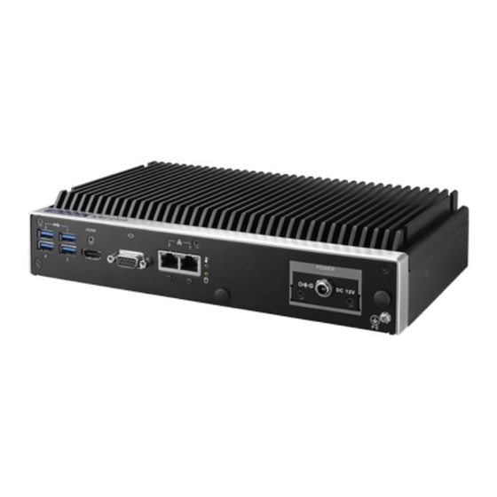
Page 42: Ark-2250 External I/O
2.3.1 ARK-2250 External I/O 图 2.2:ARK-2250 IO 接口图 ARK-2250 User Manual... - Page 43 2.3.1.1 COM Connector ARK-2250 provides four D-sub 9-pin connectors, which offers RS232/422/485 serial communication interface ports. Default setting is RS-232, if you want to use RS-422/ 485, you can refer to Section 3.4.2 BIOS Setup. 1 2 3 4 5 6 7 8 9 Figure 2.3 COM Connector Table 2.3: COM Connector Pin Assignments...
- Page 44 MDI2+ MDI2- MDI3+ MDI3- 2.3.1.3 Audio Connector ARK-2250 offers stereo audio ports by three phone jack connectors of Line_Out, Line_In and Mic_In. The audio chip is controlled by ALC888S, and it’s compliant with Azalea standard. Figure 2.5 Audio Connector Table 2.5: Audio Connector Pin Assignments Signal Name Mic_In Line_In...
- Page 45 2.3.1.5 VGA Connector ARK-2250 provides a high resolution VGA interface connected by a D-sub 15-pin connector to support a VGA CRT monitor, supports display resolutions of up to 2048 x 1152 @ 60Hz. Figure 2.7 VGA Connector Table 2.7: VGA Pin Assignments Signal Name Signal Name Green...
-
Page 46: Installation
Installation 2.4.1 Memory Installation Unscrew the 4 screws on the top cover. (Please use the tool in the accessory box.) Remove the top cover and install the memory into the memory socket. Replace the top cover. ARK-2250 User Manual... -
Page 47: Hdd/Ssd Installation
2.4.2 HDD/SSD Installation Unscrew the 4 screws on the bottom cover, and the 4 screws on both sides of ARK-2250. Unscrew the 4 screws on the HDD bay. ARK-2250 User Manual... - Page 48 Install the HDD/SSD into the HDD bay, and fix the HDD onto the bracket. Fix the 4 screws back onto the HDD bay. Replace the bottom cover and fix the 8 screws back onto the system. ARK-2250 User Manual...
-
Page 49: Msata Installation
2.4.3 mSATA Installation Unscrew the 4 screws on the bottom cover, and the 4 screws on both sides of ARK-2250. Put the mSATA module onto the mSATA slot (CN15), and fasten the 2 screws back on the mSATA module. Replace the bottom cover and fasten the 8 screws back onto the system. ARK-2250 User Manual... -
Page 50: Power Module (Mioe-Pwr2) Installation (Option)
2.4.4 Power Module (MIOe-PWR2) Installation (Option) Remove the 4 screws on the top cover. (Please use the tool in the accessory box.) Remove the 2 screws on the power bracket for the original DC jack on the front panel. ARK-2250 User Manual... - Page 51 Unscrew the 4 screws on the bottom cover and on both sides of ARK-2250. Remove the original internal power cable from the M/B. ARK-2250 User Manual...
- Page 52 Link the MIOe-PWR2 internal power cable from M/B to the power board. Turn to the top side, and fasten the 4 screws for the power board, and tape 3 thermal pads on the red marks. ARK-2250 User Manual...
-
Page 53: Idoor Module Installation (Option)
Screw the new power bracket for MIOe-PWR2 on the front panel. Replace the bottom cover and the 8 screws back onto the system. Replace the top cover and the 4 screws. 2.4.5 iDoor Module Installation (Option) Please refer to the start up manual in the iDoor kit. 2.4.6 2nd Layer MIOe Module Installation (Option) Please refer to the start up manual in the iDoor kit. - Page 54 ARK-2250 User Manual...
-
Page 55: Chapter 3 Bios Settings
Chapter BIOS Settings... -
Page 56: Bios Setup
BIOS Setup With the AMIBIOS setup program, you can modify BIOS settings and control the var- ious system features. This chapter describes the basic navigation of the ARK-2250 BIOS setup screens. Figure 3.1 Setup program initial screen AMI's BIOS ROM has a built-in Setup program that allows users to modify the basic system configuration. -
Page 57: Main Setup
3.2.1 Main Setup When users first enter the BIOS Setup Utility, users will enter the Main setup screen. Users can always return to the Main setup screen by selecting the Main tab. There are two Main Setup options. They are described in this section. The Main BIOS Setup screen is shown below. -
Page 58: Advanced Bios Features Setup
3.2.2 Advanced BIOS Features Setup Select the Advanced tab from the ARK-2250 setup screen to enter the Advanced BIOS Setup screen. You can select any of the items in the left frame of the screen, such as CPU Configuration, to go to the sub menu for that item. You can display an Advanced BIOS Setup option by highlighting it using the <Arrow>... - Page 59 3.2.2.1 ACPI Settings Figure 3.4 ACPI Setting Enable ACPI Auto Configuration This item allows users to enable or disable BIOS ACPI auto configuration. Enable Hibernation This item allows users to enable or disable hibernation. ACPI Sleep State This item allows users to set the ACPI sleep state.
- Page 60 3.2.2.2 Super I/O Configuration Serial Port 1 Configuration Set Parameters of Serial Port 1 (COMA). Serial Port 2 Configuration Set Parameters of Serial Port 2 (COMB). Serial Port 3 Configuration Set Parameters of Serial Port 3 (COMC). ...
- Page 61 3.2.2.3 Embedded Controller Configuration EC Hardware Monitor This page display all information about system Temperature/Voltage/Current. EC Power Saving Mode This item allows users to set board’s power saving mode when off. EC Watch Dog Function This item allows users to select EC watchdog timer. ARK-2250 User Manual...
- Page 62 3.2.2.4 S5 RTC Wake Settings Wake system from S5 Enable or disable System wake on alarm event. Select FixedTime, system will wake on the hr:min:sec specified. ARK-2250 User Manual...
- Page 63 3.2.2.5 Serial Port Console Redirection Console Redirection This item allows users to enable or disable console redirection for Microsoft Windows Emergency Management Services (EMS). Console Redirection This item allows users to configuration console redirection detail settings. ARK-2250 User Manual...
- Page 64 3.2.2.6 CPU Configuration Figure 3.5 Intel Fast Flash Standby Limit CPUID Maximum Disabled for Windows XP. Execute Disable Bit XD can prevent certain classes of malicious buffer overflow attacks when com- bined with a supporting OS (Windows Server 2003 SP1, Windows XP SP2, SuSE Linux 9.2, RedHat Enterprise 3 Update 3.) ...
- Page 65 3.2.2.7 PPM Configuration CPU C state Report Enable/Disable CPU C state report to OS. Max CPU C-state This option controls Max C state that the processor will support. ARK-2250 User Manual...
- Page 66 3.2.2.8 IDE Configuration Serial-ATA (SATA) Enable / Disable Serial ATA. SATA Speed Support SATA Speed Support Gen1 or Gen2. SATA Mode Select IDE / AHCI. Serial-ATA Port 0 / Port1 Enable / Disable Serial ATA Port0 / Port1. ...
- Page 67 3.2.2.9 CSM Configuration CSM Support Enable/Disable CSM Support. GateA20 Active UPON REQUEST - GA20 can be disabled using BIOS services. We suggest you do not disable GA20 as this option is useful when any RT code is executed above 1MB.
- Page 68 3.2.2.10 Trusted Computing Trusted Computing Enables or Disables BIOS support for security devices. OS will not show Secu- rity Device. TCG EFI protocol and INT1A interface will not be available. ARK-2250 User Manual...
- Page 69 3.2.2.11 USB Configuration Legacy USB Support Enables Legacy USB support. AUTO option disables legacy support if no USB devices are connected. DISABLE option will keep USB devices available only for EFI applications. XHCI Hand-off This is a workaround for OS without XHCI hand-off support. The XHCI owner- ship change should be claimed by XHCI driver.
-
Page 70: Security Configuration
3.2.3 Security Configuration TXE HMRFPO Disable TXE Firmware Update TXE EOP Message Send EOP message before entering OS TXE Unconfiguration Perform Revert TXE settings to factory defaults ARK-2250 User Manual... - Page 71 3.2.3.1 Chipset Configuration North Bridge Details for North Bridge items. South Bridge Details for South Bridge items. 3.2.3.2 North Bridge ARK-2250 User Manual...
- Page 72 Intel IGD Configuration Config Intel IGD settings. Max TOLUD Maximum value of TOLUD. 3.2.3.3 Intel IGD Configuration Primary IGFX Boot Display Select the Video Device which will be activated during POST. This has no effect if external graphics are present. Secondary boot display selection will appear based on your selection.
- Page 73 3.2.3.4 South Bridge Azalia HD Audio Azalia HD Audio options. USB Configuration USB Configuration Settings. PCI Express Configuration PCI Express Configuration settings. High Precision Timer Enables or disables the high precision timer. LAN1 Controller Enable or Disable the LAN1. ...
- Page 74 3.2.3.5 Azalia HD Audio Audio Controller Control Detection of the Azalia device. Disabled = Azalia will be unconditionally disabled. Enabled = Azalia will be unconditionally Enabled. Auto = Azalia will be enabled if present disabled otherwise. Azalia HDMI Codec Enable/Disable internal HDMI codec for Azalia ...
- Page 75 3.2.3.6 USB Configuration OS Selection OS Selection to choose Windows 8.X / Windows 7. XHCI Mode Mode of operation of xHCI controller. USB 2.0(EHCI) Support Control the USB EHCI (USB 2.0) functions. One EHCI controller must always be enabled.
- Page 76 3.2.3.7 PCI Express Configuration PCI Express Port0 / Port2 Enable or Disable the PCI Express Port0 / Port 2 in the chipset. PCIe Speed Configure PCIe Port Speed. ARK-2250 User Manual...
-
Page 77: Boot Settings
3.2.4 Boot Settings Setup Prompt Timeout Number of seconds that the firmware will wait before initiating the original default boot selection. A value of 0 indicates that the default boot selection is to be initiated immediately on boot. A value of 65535 (0xFFFF) indicates that firm- ware will wait for user input before booting. -
Page 78: Security Setup
3.2.5 Security Setup Select Security Setup from the ARK-2250 Setup main BIOS setup menu. All Security Setup options, such as password protection is described in this section. To access the sub menu for the following items, select the item and press <Enter>: ... -
Page 79: Save & Exit
3.2.6 Save & Exit Save Changes and Exit This item allows you to exit system setup after saving the changes. Discard Changes and Exit This item allows you to exit system setup without saving any changes. Save Changes and Reset This item allows you to reset the system after saving the changes. - Page 80 ARK-2250 User Manual...
-
Page 81: Appendix A Watchdog Timer Sample Code
Appendix Watchdog Timer Sample Code... -
Page 82: Ec Watchdog Timer Sample Code
EC Watchdog Timer sample code EC_Command_Port = 0x29Ah EC_Data_Port = 0x299h Write EC HW ram = 0x89 Watch dog event flag = 0x57 Watchdog reset delay time = 0x5E Reset event = 0x04 Start WDT function = 0x28 ==================================================== .model small .486p .stack 256 .data... - Page 83 ARK-2250 User Manual...
- Page 84 No part of this publication may be reproduced in any form or by any means, electronic, photocopying, recording or otherwise, without prior written permis- sion of the publisher. All brand and product names are trademarks or registered trademarks of their respective companies. © Advantech Co., Ltd. 2017...
Need help?
Do you have a question about the ARK-2250L-U6A1E and is the answer not in the manual?
Questions and answers