Table of Contents
Advertisement
Quick Links
Advertisement
Table of Contents

Subscribe to Our Youtube Channel
Related Manuals for multicomp pro MP730424


Summary of Contents for multicomp pro MP730424
- Page 1 MP730424 Digital Multimeter User Manual...
-
Page 2: Table Of Contents
Table of Contents 1.Safety Information ....................1 Safety Terms and Symbols ....................1 General Safety Requirements ....................2 Measurement Limits ......................3 Main Input Terminals (HI Input and LO Input) Measurement Limits ............3 Current Input Terminal (I) Measurement Limits ..................4 Sense Terminals (HI Sense and LO Sense) Measurement Limits .............. - Page 3 Math ..........................27 Max/Min ..............................27 dB/dBm ..............................27 Relative Value ............................28 Data Record Function ......................29 Manual Record ............................29 Auto Record ............................30 Port Configuration ......................31 Serial ............................... 31 Language ..............................31 Backlight ..............................31 Clock ............................... 31 Default ..............................
-
Page 4: Safety Information
1. Safety Information Safety Terms and Symbols Safety Terms Terms in this Manual. The following terms may appear in this manual: Warning: Warning indicates the conditions or practices that could result in injury or loss of life. Caution: Caution indicates the conditions or practices that could result in damage to this product or other property. -
Page 5: General Safety Requirements
General Safety Requirements Before any operations, please read the following safety precautions to avoid any possible bodily injury and prevent this product or any other products connected from damage. In order to avoid any contingent danger, this product is only used within the range specified. -
Page 6: Measurement Limits
Measurement Limits The protection circuitry of the multimeter can prevent damage to the instrument and protect against the danger of electric shock, when the measurement limits are not exceeded. To ensure safe operation of the instrument, do not exceed the measurement limits shown on the front panel, it is defined as follows: The user-replaceable 10A current-protection fuse is on the front panel. -
Page 7: Current Input Terminal (I) Measurement Limits
Current Input Terminal (I) Measurement Limits The Measurement Limit from the current input terminal (I) to the LO Input terminal is 10 A (DC or AC). Note that the current input terminals will always be at approximately the same voltage as the LO Input terminal, unless a current protection fuse is open. Sense Terminals (HI Sense and LO Sense) Measurement Limits The HI and LO sense terminals are used for four-wire resistance measurements. -
Page 8: Quick Start
2. Quick Start General Inspection After you get a new multimeter, it is recommended that you should make a check on the instrument according to the following steps: 1. Check whether there is any damage caused by transportation. If the packing boxes or foam cushions are found to have serious damage, keep them in a safe place until the complete instrument and accessories have passed the electrical and mechanical tests. -
Page 9: Foot Stool Adjustment
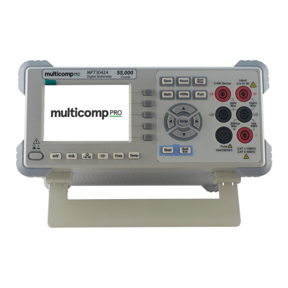
Support Feet Adjustment Unfold the support feet on the bottom of the multimeter. Front Panel Overview Figure 2-1 Front panel overview Item Name Description Display the user interface Menu selection Activate the corresponding menu Keys Operation Keys Save Collect data in manual record. The instrument saves current reading each time the Save key is pressed. - Page 10 HI and LO Input Signal input terminals, used for voltage, resistance, Terminals continuity, frequency (period), capacitance, diode, and temperature test measurements. Range/Direction Keys When the Range softkey is shown on the right menu, you can press the key to switch between auto and manual range.
-
Page 11: Rear Panel Overview
Rear Panel Overview Figure 2-2 Rear panel overview Item Name Description RS232 Connect the PC through this port. Line Fuse The fuse rating is . To replace the fuse, see page 250 V, F1AL 41, Appendix C: Line Fuse Replacement. AC Mains Input AC mains input connector. -
Page 12: User Interface
User Interface Trigger Mode Status Icon Reading Operation Menus Unit Range Function Trigger Mode Status Icon Display Description Icon Description Trigger Auto trigger Auto record function is running Manual record Figure 2-3 User interface (Single display) Primary function reading Secondary function Primary function Figure 2-4 User interface (Dual display) -
Page 13: Power On
Power On (1) Connect the instrument to the AC supply using the supplied power cord. Warning: To avoid electric shock, the instrument must be grounded properly. (2) Press down the power button at the front panel, the screen shows the boot screen. -
Page 14: Measurement Connections
Measurement Connections After selecting the desired measurement function, please connect the signal (device) under test to the multimeter according to the method below. To avoid instrument damage, do not discretionarily switch the measurement function when measuring. DC Voltage Measurement AC Voltage Measurement DC Voltage AC Voltage DC Current Measurement... - Page 15 Capacitance Measurement Frequency/Period Measurement Capacitance AC Signal Temperature Measurement Temp Transducer...
-
Page 16: Functions And Operations
3. Functions and Operations To Set The Range The instrument provides auto and manual range. In auto range, the multimeter selects a proper range automatically according to the input signal; in manual range, you can use the front panel key or menu softkey to set the range. The auto range can bring a lot of convenience for users while the manual range provides higher reading precision. -
Page 17: Measurement Speed
Measurement Speed The instrument provides three types of measurement speed: "Low" speed is 4 reading/s; "Mid" speed is 16 reading/s; "High" speed is 65 reading/s. In DCV, ACV, DCI, ACI and 2-wire / 4-wire resistance measurements, the measurement speed is selectable. Basic Measurement Functions Measuring DC Voltage This section describes how to configure DC voltage measurements. -
Page 18: Measuring Ac Voltage
5. Set the relative value. Press the Rel softkey to turn on or off the relative operation. For relative operation, the multimeter subtracts the pre-specified value of REL operation from the actual measurement result and displays the result. See page 28, Relative Value. Measuring AC Voltage This section describes how to configure AC voltage measurements. -
Page 19: Measuring Dc Current
Measuring DC Current This section describes how to configure DC current measurements. Operating Steps: 1. Enable the DCI measurement. Press on the front panel to enter DCI measurement mode. 2. Connect the test lead. DC Current 3. Set the range. Press the Range softkey to set the range. -
Page 20: Measuring Ac Current
Measuring AC Current This section describes how to configure AC current measurements. Operating Steps: 1. Enable the ACI measurement. Press on the front panel, press it again to enter ACI measurement mode. 2. Connect the test lead. AC Current 3. Set the range. Press the Range softkey to set the range. -
Page 21: Measuring Resistance
Measuring Resistance This section describes how to configure 2-wire and 4-wire resistance measurements. The multimeter provides 2-wire and 4-wire resistance measurements. When the measured resistance is lower than 100 kΩ, the 4-wire resistance measurement is recommended to reduce the measurement error caused by test lead resistance and contact resistance between the probe and the testing point, because these two resistances can not be ignored any more, compared to the measured resistance. -
Page 22: Continuity Test
4-wire Resistance 3. Set the range. Press the Range softkey to set the range. Auto range automatically selects the range for the measurement based on the input. Note: 1000 V input protection is available in all ranges. 10% over range for all ranges except 50 MΩ range. ... -
Page 23: Diode Test
2. Connect the test lead. Open or Closed Circuit 3. Set the beeper. Press the Beeper softkey to enable or disable the beeper. When the beeper is enabled, the reading is below 30 Ω, the multimeter will beep continuously. 4. Set the short-circuit resistance. Press the Threshold softkey to set the short-circuit resistance. -
Page 24: Measuring Capacitance
2. Connect the test lead. Forward Bias 3. Set the beeper. Press the Beeper softkey to enable or disable the beeper. When the beeper is enabled, the diode is connected, the multimeter will beep continuously. 4. Diode measurements behave as follows: Forward pressure Display and beep drop of diode... -
Page 25: Measuring Frequency And Period
2. Connect the test lead. Capacitance Tip: Please short contact the two feet of an electrolytic capacitor by using a test lead before measuring the electrolytic capacitor. 3. Set the range. Press the Range softkey to set the range. Auto range automatically selects the range for the measurement based on the input. - Page 26 Press on the front, in the right menu, press the model soft key to switch and select Freq/Period measurement 2. Connect the test lead. AC Signal 3. Note Frequency range: 20 Hz to 60 MHz. 750 V input protection is available in all ranges. ...
-
Page 27: Measuring Temperature
Measuring Temperature This section describes how to configure temperature measurements. Temperature measurements require a temperature transducer probe. The supported probes are type KITS90 and PT100 sensor. Operating Steps: 1. Enable the temperature measurement. Press on the front panel to enter temperature measurement mode. 2. -
Page 28: Dual Display
Press the Rel softkey to turn on or off the relative operation. For relative operation, the multimeter subtracts the pre-specified value of REL operation from the actual measurement result and displays the result. See page 28, Relative Value. Dual Display Using dual display function, you can view the readings of two measurement functions simultaneously. -
Page 29: Data Hold
Note: The multimeter makes the primary and secondary measurements alternately, the primary and secondary readings update respectively. If the Max/Min, dB/dBm, or relative value of the math operation is turned on in the main display, the math operation is automatically turned off when dual display is turned on. -
Page 30: Math
Math The multimeter provides these math functions: Max/Min, dB/dBm and relative. Only one operation can be enabled in the Max/Min, dB/dBm, or relative operation. Max/Min The Max/Min operation is used to calculate the max, min and average of the readings during the measurement period Press the front panel key, press the Max/Min softkey, press the Static softkey to... -
Page 31: Relative Value
dB Function dB represents the relative value which is used in the relative operation of dBm value. When enabled, the multimeter calculates the dBm value of the reading and subtracts the preset dB from this value and then displays the result: dB = 10 x Log ( reading / reference resistance / 1 mW) - dB preset... -
Page 32: Data Record Function
Data Record Function Data record function includes manual record and auto record. You can use any or both functions to record the data. Manual and automatic records share a table of data stored in internal storage.The maximum number of recorded points is 1000.After collecting the data, it can be exported to the computer. -
Page 33: Auto Record
Auto Record 1. Configure the parameters: Press the front panel key, press the Auto softkey. Press the Point softkey to specify the total number of readings to record. The range is 1 to 1000. Press the Interval softkey to specify the time interval between readings. The range is 15 ms to 9999.999 s. -
Page 34: Port Configuration
Port Configuration You can configure the port parameters in port configuration. Serial Press the front panel key, press the Serial softkey to access the serial port setting menu. Press the Baud softkey to select the desired baud rate from 2400, 4800, 9600, 19200, 38400, 57600 or 115200. - Page 35 Type Item Value Baud 115200 Data bits Port Odd-Even None Stop bit Utility BLight 100% dB/dBm Off/On Function 50Ω Math Rel R 0Ω Db Rel Max/Min Static Auto Clear Manual Clear Record Point Interval Aoto On/Off Run/Stop Beeper 50Ω Threshold Freq Model Freq ℃...
-
Page 36: Measurement Tutorial
4. Measurement Tutorial Loading Errors (DC Voltage) Measurement loading errors occur when the resistance of the DUT(Device-Under-Test) is an appreciable percentage of the multimeter's input resistance, as shown below. Ideal Meter = ideal DUT voltage = DUT source resistance = multimeter input resistance ... -
Page 37: True Rms Ac Measurements
True RMS AC Measurements The AC measurement of the multimeter has true RMS response. Power dissipated in a resistor is proportional to the square of an applied voltage, independent of the wave shape of the signal. This multimeter accurately measures true rms voltage or current, as long as the wave shape contains negligible energy above the meter’s effective bandwidth. -
Page 38: Loading Errors (Ac Voltage)
Loading Errors (AC Voltage) In the AC voltage function, the input impedance of the multimeter appears as a 1 MΩ resistance in parallel with 100 pF of capacitance. The cabling that you use to connect signals to the multimeter also adds capacitance and loading. The table below shows the multimeter's approximate input resistance at various frequencies. -
Page 39: Crest Factor Errors (Non-Sinusoidal Inputs)
Crest Factor Errors (non-sinusoidal inputs) A common misconception is that because an AC multimeter is true RMS, its sine wave accuracy specifications apply to all waveforms. Actually, the shape of the input signal dramatically affects measurement accuracy. A common way to describe signal wave shapes is “crest factor”. -
Page 40: Troubleshooting
(see page 41, Appendix C: Line Fuse Replacement). 3) Restart the instrument after the steps above. 4) If the problem still exists, please contact MULTICOMP PRO for our service. 2. The reading does not change when a current signal is input. -
Page 41: Technical Specifications
6. Technical Specifications Function Range Resolution Accuracy: ± (% of reading + LSB) 50.000 mV 0.001 mV 0.1% + 10 500.00 mV 0.01 mV 0.025% + 5 5.0000 V 0.0001 V 0.025% + 5 DC Voltage 50.000 V 0.001 V 0.03% + 5 500.00 V 0.01 V... - Page 42 [1] Specifications are for 30-minute warm-up, "Low" measurement rate and calibration temperature 18℃ - 28℃. [2] 10% over range on all ranges, except 1,000 V DCV, 750 ACV, 10 A DCI, 10 A ACI, 50 MΩ resistance, and 50 mF capacitance. [3] For each additional volt over ±...
-
Page 43: Appendix
7. Appendix Appendix A: Enclosure Standard Accessories (subject to final delivery): Spare Fuse Power Cord Test lead Crocodile clip Quick Guide Appendix B: General Care and Cleaning General Care Do not store or leave the instrument where the liquid crystal display will be exposed to direct sunlight for long periods of time. -
Page 44: Appendix C: Line Fuse Replacement
Appendix C: Line Fuse Replacement The line fuse is in the plastic fuse box below the power line input on the rear panel. Warning: Disconnect from the mains and remove all test leads connected to the instrument before replacing the line fuse. Use only the correct fuse type.
Need help?
Do you have a question about the MP730424 and is the answer not in the manual?
Questions and answers