Table of Contents
Advertisement
Advertisement
Table of Contents

Related Manuals for multicomp pro MP730026


Summary of Contents for multicomp pro MP730026
- Page 1 Digital Multimeter Model MP730026...
-
Page 2: Table Of Contents
Table of Contents 1.Safety Information ....................1 Safety Considerations ......................1 Measurement Category ....................... 3 Safety Terms and Symbols ....................4 2.Quick Start ........................ 5 General Inspection ......................5 Install the Batteries ......................5 Adjusting the Tilt Stand ....................... 6 Power On ........................... - Page 3 Buzzer Feature ........................16 5.To Connect with Mobile Device – Only for MP730026 ..Error! Bookmark not defined. Android App ................Error! Bookmark not defined. How to Connect with Android Device ............Error! Bookmark not defined. User Interface in Android App ..............Error! Bookmark not defined.
-
Page 4: Safety Information
User Manual 1. Safety Information Safety Considerations Before any operations, please read the following safety precautions to avoid any possible bodily injury and prevent damage to this product or any other products connected. To avoid any contingent danger, use this product only as specified. EC Declaration of Conformity: Meets intent of Directive 2004/108/EC for Electromagnetic Compatibility. - Page 5 User Manual When servicing the multimeter, use only the specified replacement parts. Use caution when working above 60 VDC, 30 VAC RMS, or 42.4 V peak. Such voltages pose a shock hazard. When using the test leads, keep your fingers behind the finger guards on the test ...
-
Page 6: Measurement Category
User Manual Measurement Category The multimeter has a safety rating of 1000 V, CAT III and 600 V, CAT IV. Measurement category definition Measurement CAT I applies to measurements performed on circuits not directly connected to the AC mains. Examples are measurements on circuits not derived from the AC mains and specially protected (internal) mains- derived circuits. -
Page 7: Safety Terms And Symbols
User Manual Safety Terms and Symbols Safety Terms Terms in this Manual. The following terms may appear in this manual: Warning: Warning indicates the conditions or practices that could result in personal injury or death. Caution: Caution indicates the conditions or practices that could result in damage to this product or other property. -
Page 8: Quick Start
User Manual 2. Quick Start General Inspection After you get a new multimeter, make a check on the instrument according to the following steps: 1. Check whether there is any damage caused by transportation. If the packing boxes or foam cushions are found to have serious damage, keep them in a safe place until the complete instrument and accessories have passed the electrical and mechanical tests. -
Page 9: Adjusting The Tilt Stand
User Manual Caution: To avoid instruments being damage from battery leakage, always remove the batteries and store them separately if the multimeter is not going to be used for a long period. Adjusting the Tilt Stand Pull the tilt stand outward to its maximum reach (about 85° to the meter body). Power On (1) To power ON the multimeter, turn the rotary switch to any other position except (2) To power OFF the multimeter, turn the rotary switch to the... -
Page 10: Multimeter In Brief
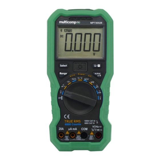
2 seconds to enter the auto ranging mode. Note: Manual range is not available when measuring capacitance. Multimeter in Brief Front panel Figure 2-1 Front panel overview (MP730026 with hFE is shown for example) Description Details ① Display screen Page 9 ②... -
Page 11: Rotary Switch
User Manual ④ Input terminals Page 10 ⑤ Transistor test holes Page 15 (only for specific models) ⑥ LED indicator ⑦ Non-contact voltage detector (NCV) Page 14 ⑧ Flashlight Page 6 Rotary switch Position Description Details Power off Page 6 DC or AC voltage measurement Page 12 DC or AC voltage measurement... -
Page 12: Display Screen
Page 16 Select frequency/duty cycle Page 14 Measuring frequency in AC voltage/current mode Page 16 Relative Measurements Page Error! Bluetooth Bookmar (only for MP730026) defined. Display screen Figure 2-2 Display screen Symbol Description Details Page Error! Bluetooth enabled Bookmark not defined. -
Page 13: Input Terminals
User Manual Page 12 and Page 14 Battery is low Page 5 Measurement display ("OL" is short for overload, indicates the reading exceeds the display range) Non-contact Voltage Detect Page 14 Measuring units Page 10 Measurement units Sign Description Mega 1E+06 (1000000) kilo 1E+03 (1000) - Page 14 User Manual Warning: Before starting any measurement, observe the rotary switch position of the multimeter, and then connect the test leads to the correct terminals. Caution: To avoid damaging the multimeter, do not exceed the rated input limit. Rotary switch Input terminals Overload protection position...
-
Page 15: Making Measurements
User Manual 3. Making Measurements Measuring AC or DC Voltage Warning: Do not measure any voltage of over 1000 Vdc or 750 Vac rms to avoid instrument damage or electric shock. Do not apply more than 1000 Vdc or 750 Vac rms between the common terminal and the earth ground to avoid instrument damage or electric shock. -
Page 16: Testing For Continuity
User Manual Testing for Continuity Caution: To avoid possible damage to your multimeter or to the equipment under test, disconnect the circuit power and discharge all high-voltage capacitors before testing for continuity. (1) Rotate the rotary switch to . Press once to enter continuity testing mode, will be displayed. -
Page 17: Measuring Frequency
User Manual (3) Probe the test points and read the display. Measuring Frequency (1) Rotate the rotary switch to (2) Connect the black test lead to the terminal and the red test lead to the terminal. (3) Probe the test points and read the display. (4) Press to switch between the frequency and duty cycle measurements. -
Page 18: Measuring Transistor - Only For Specific Models
User Manual (3) Place the top of the meter very close to the voltage source as shown in the figure. (4) If voltage is detected, the LED above the display will flash, and the meter will beep. Measuring Transistor — Only for specific models (1) Rotate the rotary switch to (2) Verify the type of the transistor is NPN or PNP, and locate the Emitter, Base and Collector leads. -
Page 19: Multimeter Features
User Manual 4. Multimeter Features Data Hold Mode (1) Press to freeze the display during measurement, will be shown on the display. (2) Press again to exit this mode. Making Relative Measurements When making relative measurements, reading is the difference between a stored reference value and the input signal. -
Page 20: To Connect With Computer - Only For Mp730026
The computer must be running the Windows operating system (Windows 10, Windows 8, Windows 7, Windows Vista and Windows XP). MP730026 supports communications with a computer through Bluetooth. You can use the free multimeterBLE software on computer to monitor the measurements, perform remote control, view trending graphs, etc. - Page 21 User Manual (3) Select "I accept the agreement", and then click "Next".
- Page 22 User Manual (4) Select the destination folder, and then click "Next". (5) Click "Install".
- Page 23 User Manual (6) Uncheck "View the Release Notes", and click "Finish" to exit Setup. (7) Plug the Bluetooth USB adapter into a USB port on your computer. Right click [Computer], you can find it on the desktop, or in [Start] menu. In the drop down menu, click on [Manage], the “Computer Management”...
- Page 24 User Manual Note: If an unknown device is displayed, try to install the driver manually following the steps below. How to install the driver manually Right click the unknown device icon, in the drop down menu, click "Update Driver Software...".
- Page 25 User Manual Select "Browse my computer for driver software". Select a directory path for the driver, and click "Next". After installing successfully, click "Close". In Device Manager, check if "TI CC2540 USB CDC Serial Port (COM#)" is displayed under Ports (COM & LPT).
-
Page 26: Step 3: Connect To Multimeterble Software
User Manual Step 3: Connect to multimeterBLE software (1) After installing the Bluetooth USB adapter driver successfully, run the multimeterBLE software, the configure dialog box appears. Make sure that the Bluetooth USB adapter is plugged into the computer. To find the “Port” (COM #), you will need to look for it under "Ports (COM & LPT)" in Device Manager window. - Page 27 User Manual scan is finished, select the desired multimeter in the device list. Click the "Connect" button. (4) The measurements will be shown if the connection is successful. You can tap on the softkey on the right to add another multimeter.
-
Page 28: User Interface In Multimeterble Software
User Manual User Interface in MultimeterBLE Software Single Device View Single Device View Move the cursor here to show , click to delete the device Add device Single device view Multi-device view Start offline record Read offline record Graph&Table view About Scroll to show other device... -
Page 29: Operations In Multimeterble Software
"Function" on the top right, in the drop down menu, check "Singleton". Multimeter Offline Record (PC Software) When measuring with MP730026, you can use PC software to send a command, the multimeter will start recording the measurements. After receiving the command, the connection will be disconnected automatically. - Page 30 User Manual record function may not work correctly. Please check the batteries of the meter to ensure them in a good state. (1) Connect the multimeterBLE software with the multimeter, see " How to Connect with " on P17. Computer (2) On software interface, click the softkey on the right, a dialog will show.
- Page 31 User Manual (7) Click "Open Directory" to open the directory where the CSV files are saved.
-
Page 32: Technical Specifications
User Manual 6. Technical Specifications All these specifications apply to the multimeter unless otherwise explanation. Standard conditions: The environment temperature is 18℃ to 28℃, the relative humidity is less than 80%. Note: When measuring AC voltage/current or capacitance, accuracy guarantee range is 5% to 100% of the range. - Page 33 Characteristics Instruction Display 5999 Frequency Response (Hz) (40 - 1000) Hz 3 times/second Sample rate for digital data MO730026 Without Bluetooth √ MP730026 √ Auto ranging √ True RMS √ Diodes Test √ Sleep Mode √ Continuity Test √ (The "...
-
Page 34: Appendix
User Manual 7. Appendix Appendix A: Enclosure Standard Accessories: K-type Bolt driver Test lead Quick guide 9V battery (6F22) thermocouple Crocodile clip (only for MP730026) Options: Bluetooth USB adapter to PC (only for MP730026) -
Page 35: Appendix B: General Care And Cleaning
User Manual Appendix B: General Care and Cleaning Warning: To avoid electrical shock or damage to the multimeter, ensure that the insides of the casing stay dry at all times. Cleaning To clean the instrument exterior, perform the following steps: Wipe the dust from the instrument surface with a soft cloth.
Need help?
Do you have a question about the MP730026 and is the answer not in the manual?
Questions and answers