Table of Contents
Advertisement
Available languages
Available languages
Quick Links
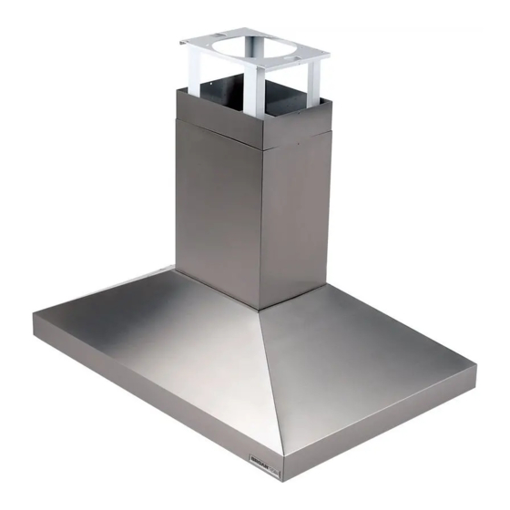
63000EX Series
Broan-NuTone LLC. 926 West State Street, Hartford, WI 53027
NuTone Inc., 4820 Red Bank Road, Cincinnati, OH 45227
Broan-NuTone Canada Inc.1140 Tristar Drive, Mississauga, Ontario L5T 1H9
ENGLISH....................................2
FRANÇAIS...............................13
ESPAÑOL.................................25
Advertisement
Table of Contents

Subscribe to Our Youtube Channel
Related Manuals for Broan 637004EX


Summary of Contents for Broan 637004EX
- Page 1 63000EX Series ENGLISH........2 FRANÇAIS.......13 ESPAÑOL.........25 Broan-NuTone LLC. 926 West State Street, Hartford, WI 53027 NuTone Inc., 4820 Red Bank Road, Cincinnati, OH 45227 Broan-NuTone Canada Inc.1140 Tristar Drive, Mississauga, Ontario L5T 1H9...
- Page 2 READ AND SAVE THESE INSTRUCTIONS INTENDED FOR DOMESTIC COOKING ONLY WARNING TO REDUCE THE RISK OF FIRE, ELECTRIC SHOCK, OR INJURY TO PERSONS, OBSERVE THE FOLLOWING: 1. Use this unit only in the manner intended by the manufacturer. If you have questions, contact the manufacturer at the address or telephone number listed in the warranty.
- Page 3 11. Please read specification label on product for further information and requirements. 12. To reduce the risk of fire and electric shock, install this range hood only with Broan Exterior blower models 331H, 332H, 335 or 336, or Broan In-Line Blower models HLB3, HLB6, HLB9 or HLB11.
-
Page 4: Prepare The Hood
PREPARE THE HOOD Unpack hood and check contents. You should receive: 1 - Hood DUCT COLLAR 1 - Decorative Flue Assembly 1 - Support Frame 1 - Parts Bag (B080810004) containing: 4 - Mounting Screws (6 x 70mm) 8 - Washers Ø 6.4mm 4 - Washers Ø... -
Page 5: Install The Ductwork
EXTERIOR OR IN-LINE BLOWER SELECTION CAUTION: Either an exterior blower or in-line blower may be used with this hood. The 63000EX series hood must be installed with blower models 331H, 332H, 335, 336, HLB3, HLB6, HLB9 or HLB11 only. Other Blowers cannot be substituted (Blowers sold separately). - Page 6 IN-LINE BLOWER - 6 -...
-
Page 7: Install Support System
INSTALL SUPPORT SYSTEM CROSS FRAMING DRYWALL 1. At hood location, install 2 x 4 cross framing ” between ceiling joists using dimensions shown. 2. Finish the ceiling surface. Be sure to mark the location of the ceiling joists and cross CEILING framing. - Page 8 INSTALL DUCT COLLAR MOUNTING SCREWS (3.9x9.5mm) 1. Fix the discharge collar onto the hood; it must be fixed either by means of 4 mounting screws (3,9x9,5mm). DISCHARGE COLLAR MOUNT HOOD TO SUPPORT FRAME 1. Before mount hood to support frame remove the electrical box.
- Page 9 WIRING BLOWER CONNECTION AT HOOD CAUTION: All electrical wiring should Exterior or In-Line be done by a qualified person (s) in blower accordance with all applicable codes and CONNECT: standards. This range hood must be WHITE-TO-WHITE, properly grounded. RED-TO-BLACK, GREEN-TO-GROUND. Do not turn power on at service panel until all wires have been connected.
-
Page 10: Connect Ductwork
CONNECT DUCTWORK LOWER FLUE 1. Use 8" round metal duct to connect the RETAINING discharge collar on the hood to the ductwork SCREW above. 2. Use duct tape to make all joints secure and air tight. 3. Remove the temporary retaining screw from the lower flue and set it in place on the hood. -
Page 11: Operation
OPERATION Controls BLOWER LIGHT The hood is operated using the slide controls ON / OFF SWITCH BLOWER under the front edge of the hood. SWITCH SPEED The light switch turns the halogen lights on CONTROL and off. The blower on / off switch turns the blower on to the running speed set by the blower speed control. -
Page 12: Fuse Replacement
RANTIES, EXPRESS OR IMPLIED, INCLUDING, BUT NOT LIMITED TO, IMPLIED WARRANTIES OR MERCHANT ABILITY OR FITNESS FOR A PARTICULAR PURPOSE. During this one-year period, Broan-NuTone LLC will, at its option, repair or replace, without charge, any product or part which is found to be defective under normal use and service. - Page 13 LISEZ ET CONSERVEZ CES INSTRUCTIONS SEULEMENT POUR UTILISATION DOMESTIQUE AVERTISSEMENTS POUR REDUIRE LES RISQUES D’INCENDIE, DE DECHARGES ELECTRIQUES OU DE DOMMAGES AUX PERSONNES, OBSERVEZ LES INSTRUCTIONS SUIVANTES: 1. N’utilisez cet appareil que comme cela est indiqué par le constructeur. Si vous avez des problèmes, contactez le fabriquant à...
- Page 14 12. Pour diminuer les dangers d’incendie ou de choc électrique, installer cette hotte de cuisine uniquement parmi les modèles de ventilateurs externe “Broan” modèles 331H, 332H, 335 ou 336, ou ventilateurs “In-Line, Broan” Modèles HLB3, HLB6, HLB9 ou HLB11. On ne peut pas utiliser d’autres ventilateurs (Les ventilateurs sont vendus séparément).
- Page 15 PREPAREZ LA HOTTE Enlever la hotte dans l’emballage et controller le contenu. Vous devez recevoir : COLLIER 1 - Hotte D’EVACUATION 1 - Conduit décoratif 1 - Structure de support 1 - Sachet (B080810004) avec: 4 - Vis d’assemblage (6 x 70mm) 8 - Rondelles Ø...
-
Page 16: Installation Du Systeme D'evacuation
CHOIX DE VENTILATEUR EXTERNE OU “IN-LINE” ATTENTION: avec cette hotte, on peut utiliser soit un ventilateur externe soit “In- Line”. Les hottes 63000EX series doit être installées avec un ventilateur des modèles suivants 331H, 332H, 335, 336, HLB3, HLB6, HLB9 ou HLB11 uniquement. - Page 17 VENTILATEUR IN-LINE - 17 -...
- Page 18 INSTALLATION DU SYSTEME SURFACE DU CADRE CROISÉ PLAFOND DE SUPPORT ” 1. Installez, à l’emplacement de votre hotte, un cadre croisé de 2 x 4 entre les solives du plafond en suivant les dimensions qui vous sont indiquées. 2. Perfectionnez la surface du plafond. SOLIVES DU Assurez-vous de bien marquer l’empla- PLAFOND...
- Page 19 ASSEMBLAGE DU CONDUIT DECORATIF VIS D’ASSEMBLAGE (3.9X9.5MM) 1. Fixez le conduit supérieur à la structure de support du haut avec les vis d’assemblage (3.9x9.5mm). 2. Installer le conduit inférieur pour qu’il touche le plafond et le fixer provisoirement CONDUIT à l’aide de la vis d’assemblage SUPERIEUR (3.9x9.5mm).
- Page 20 ASSEMBLAGE DE VOTRE HOTTE A LA STRUCTURE DE SUPPORT 1. Avant l’assemblage de votre hotte a la structura de support enlever la boîte de installation electrique 2. Assemblage de votre hotte a la structura de support. 3. Insérez quatre (4) boulons par le haut de votre hotte - de l’intérieur.
-
Page 21: Installation Electrique
INSTALLATION ELECTRIQUE BRANCHEMENT DU VENTILATEUR À LA HOTTE ATTENTION:L’installation électrique doit être faite par du personnel qualifié selon Ventilateur externe ou «In-Line» les normes. Cette hotte de cuisinière doit BRANCHER:LE BLANC être installée correctement. AVEC LE BLANC, LE ROUGE AVEC LE NOIR ET LE VERT à... -
Page 22: Entretien
CONNEXION DU SYSTEME CONDUIT INFERIEUR D’EVACUATION D’ASSEMBLAGE (3.9X9.5MM) 1. Reliez le collier d’évacuation qui se trouve sur votre hotte au système d’évacuation qui se trouve au-dessus au moyen d’un tuyau rond en métal de 8” (20cm). 2. Utilisez du ruban pour tuyauterie afin de rendre toutes les jonctions sures et étan- ches. - Page 23 FONCTIONNEMENT Commandes INTERRUPTEUR DE INTERRUPTEUR LA LUMIÈRE Votre hotte fonctionne grâce à des ON/OFF DU interrupteurs que vous faites glisser sur le VENTILATEUR devant de votre hotte. BOUTON RÉGLANT L’interrupteur de la lumière allume et éteint LA VITESSE DU les lampes halogènes. VENTILATEUR L’interrupteur ON/OFF du ventilateur fait fonctionner le ventilateur à...
-
Page 24: Garantie
Cette garantie ne couvre pas (a) l’entretien normal ni (b) tout article ou toute pièce qui aient subi une utilisation erronée, une négligence, un accident, un entretien erroné ou une réparation (autre que de la part de Broan-NuTone LLC), une installation défectueuse ou bien une installation ne respectant pas les instructions d’installation recommandées. La durée de toute garantie implicite est limitée à... - Page 25 LEA Y CONSERVE ESTAS INSTRUCCIONES INDICADO PARA EL USO EN COCINAS DOMESTICAS ADVERTENCIA PARA EVITAR EL RIESGO DE INCENDIO, CORTOCIRCUITO O DAÑO PARA LAS PERSONAS, OBSERVE ATENTAMENTE LAS SIGUIENTES NORMAS: 1. Use esta unidad solamente de la manera indicada por el fabricante; si tiene dudas, póngase en contacto con éste a la dirección o teléfono indicados en la garantía.
- Page 26 331H, 332H, 335 o 336 de la marca Broan o con los modelos de ventiladores In-Line HLB3, HLB6, HLB9 o HLB11 de la marca Broan. No pueden reemplazarse por otro tipo de ventiladores (Los ventiladores se venden por separado).
-
Page 27: Prepare La Campana
PREPARE LA CAMPANA Sacar la campana de l’embalaje y controlar el contenido. Recivireis: CASQUILLO 1 - Campana 1 - Tubo decorativo 1 - Armazón de soporte 1 - Bolsita (B080810004) con: 4 - Tornillos de montaje (6 x 70mm cabeza redonda) 8 - Arandelas Ø... - Page 28 SELECCIÓN DEL VENTILADOR EXTERIOR O DEL VENTILADOR IN-LINE PRECAUCIÓN: con este tipo de campana se deben utilizador tanto un ventilador exterior como un ventilador in-line. Las campanas 63000EX serie deben instalarse utilizando ventiladores de los modelos 331H, 332H, 335, 336, HLB3, HLB6, HLB9 o HLB11 únicamente.
- Page 29 VENTILADOR “IN-LINE” - 29 -...
- Page 30 INSTALACION DEL SISTEMA ENTRAMADO SUPERFICIE DEL TECHO DE SUJECION ” 1. En el sitio donde vaya a ir la campana, instale un entramado entre las vigas del techo utilizando las medidas dadas. 2. Termine la superficie del techo. Asegúrese de marcar la colocación de las vigas del techo y del entramado.
- Page 31 INSTALACION DEL TUBO TORNILLOS PARA EL DECORATIVO MONTAJE (3.9X9.5MM) 1. Sujete el tubo superior a la parte superior de la estructura de soporte de madera en la pared con los tornillos para el montaje (3.9x9.5mm). 2. Introduzca el tubo inferior hasta hacerlo tocar el techo, y fíjelo momentáneamente TUBO tornillo...
- Page 32 BASE DE LA CAMPANA PARA SUJETAR LA ESTRUCTURA DE MADERA 1. Antes de instalar la campana a la estructura quitar la caja de conexión eléctrica. 2. Sujetar la campana a la estructura de soporte. 3. Sujetar la parte superior de la vuestra campana hacia abajo con los cuatro (4) tornillos desde el interior.
-
Page 33: Instalacion Electrica
INSTALACION ELECTRICA CON.DEL VENTIL.A LA CAMPANA PRECAUCIÓN : Toda la instalación Ventilador Exterior eléctrica tiene realizada o “In-Line” CONECTE: exclusivamente por personal preparado y a EL CABLO BLANCO norma con los estándares y las reglas CON EL BLANCO, EL ROJO CON EL NEGRO Y establecidas. -
Page 34: Mantenimiento
INSTALACION DEL TUBO DE TUBO TORNILLO INFERIOR EXTRACCION MONTAJE (3.9X9.5MM) 1. Use un tubo de metal de 8” (20cm) de diámetro para unir el casquillo situado en la parte superior de la campana con el tubo de extracción. 2. Use la cinta para unir todas las junturas, de esta manera el tubo quedará... - Page 35 FUNCIONAMIENTO MANDO DE ENCEN- DIDO Y APAGADO Mandos DEL ASPIRADOR INTERRUPTOR DA La campana se pone en funcionamiento usando los mandos situados abajo de la parte frontal de la campana. CONTROL DE LA El interruptor sa luz enciende y apaga las VELOCIDAD DEL lámparas halógenas.
- Page 36 COMERCIAL O CONVE-NIENCIA PARA UN PROPOSITO ESPECIFICO. Durante el periodo de un año, Broan-NuTone LLC, si lo estima conveniente, reparará o reemplazará sin gastos para el usuario cualquier producto o parte de éste que sea defectuosos habiéndose usado correctamente. ESTA GARANTIA NO CUBRE: ESTARTER DE NEON, NEON, LÁMPARAS HALÒGENAS, LÁMPARAS DE ILUMINACIÓN.
-
Page 37: Service Parts
SERVICE PARTS 63000EX SERIES RANGE HOOD - Parts for stainless steel models shown. For service parts for black, white, polished brass, or brushed copper models, call Broan Customer Service. KEY NO. PART NO. DESCRIPTION B08087138 Grease Filter (n. 3) BE3345326... - Page 38 LISTE PIECES DE RECHANGE 63000EX SERIES RANGE HOOD - Ci-dessous liste pièces de rechange pour hottes en inox. Pour les pièces de recharge des modèles de couleurs noir, blanc, laiton jaune poli, cuivre brossé, contacter Broan Customer Service. PART N. DESCRIPTION B08087138 Filtre anti-graisse (n.
-
Page 39: Lista De Piezas De Recambio
63000EX SERIES RANGE HOOD - Aquí aparecen solamente las piezas de recambio para campanas de acero inoxidable, si desean las piezas de recambio de los modelos en blanco, negro, latón lustrado ó cobre acepillado, pónganse en contacto con el servicio al cliente de Broan. CÓD. N. PIEZA N. - Page 40 SERVICE PARTS - LISTE PIECES DE RECHANGE - LISTA DE PIEZAS DE RECAMBIO 63000EX SERIES RANGE HOOD 04307731/1N...
Need help?
Do you have a question about the 637004EX and is the answer not in the manual?
Questions and answers