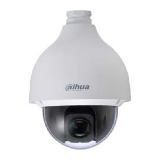
Summary of Contents for Dahua Technology 50430IC
- Page 1 4 MP HDCVI PTZ Network 50430IC Quick Start Guide Version 001.001 Dahua Technology USA Inc.
-
Page 2: Table Of Contents
Table of Contents Welcome........................1 Important Safeguards and Warnings ..............1 Electrical safety ....................1 Environmental Precautions ................2 Operation and Daily Maintenance ..............3 Lifting Appliance Requirement ................3 Warnings ......................3 FCC Information ....................4 FCC compliance: .................... 4 Legal Notices .................... -
Page 3: Welcome
1 Welcome This manual offers reference material and general information about the basic operation, maintenance, and troubleshooting of the Dahua Multi-Sensor Panoramic Camera. Read, follow, and retain the following safety instructions. Heed all warning on the unit and in the operating instructions before operating the unit. -
Page 4: Environmental Precautions
• If the unit is damaged and requires service, unplug the unit from the main AC power supply and from the PoE supply and refer to qualified service personnel. Damage may include, but is not limited to: • The power supply cord or plug is damaged. •... -
Page 5: Operation And Daily Maintenance
Operation and Daily Maintenance • Do not touch the heat dissipation component of the unit. This part of the unit is hot and may cause a burn. • Do not open or dismantle the device; there are no components that a user can fix or replace. Opening the unit may cause water leakage or expose components to direct light. -
Page 6: Fcc Information
1.3 Legal Notices Copyright This user guide is ©2017, Dahua Technology Company, LTD. This user guide is the intellectual property of Dahua Technology Company, LTD and is protected by copyright. All rights reserved. Trademarks All hardware and software product names used in this document are likely to be registered... -
Page 7: Disclaimer
1.4 Disclaimer • This user guide has been compiled with great care and the information it contains has been thoroughly reviewed and verified. The text was complete and correct at the time of printing. This guide may be periodically updated to reflect changes to the product or to correct previous information and the content of this guide can change without notice. -
Page 8: Unpacking
2 Unpacking This equipment should be unpacked and handled with care. If an item appears to have sustained damage during shipping, notify the shipper immediately. Verify that all the parts listed below are included. If an item is missing, contact customer support or your local representative. -
Page 9: Installation And Configuration
3 Installation and Configuration 3.1 Framework and Dimensions The following figures show the dimensions of the device in mm (in.). These images are intended as a reference only. Figure 3-1: Dimensions for 50430IC... -
Page 10: Wiring
3.2 Wiring The dome camera includes the following wiring bundles: Wire Color Connection Power 24 VAC Yellow/Green Earth Ground Black 24 VAC Alarm Alarm IN 1 Brown Alarm IN 2 Yellow/Green Alarm GND Blue Alarm OUT 1 Green Alarm COM 1 Video Pink Video Out... -
Page 11: Alarm Output - Level Application
Alarm Output – Level Application Use this alarm output configuration if the output triggers an external device by increasing the voltage. The alarm must increase the external pull-up resistance to trigger (high level) the device. The maximum external pull-up level is 5 V and the maximum port current is 5 mA. Once the output increases the pull-up resistance, the alarm decreases the output voltage to the normal state (low level) at less than 0.8 V. -
Page 12: Device Installation
4 Device Installation This section details installing the camera to a solid wall or to a ceiling, in an outdoor or an indoor environment. Note that the wall or ceiling must be capable of supporting a minimum of eight (8) times the weight of the camera and a bracket (if used). -
Page 13: Cable Requirements
4.1 Cable Requirements The HDCVI PTZ requires the following minimum specifications for the coaxial cable used to transmit video: • 75 Ohm Resistance • Full-cable with copper conductor • 95% knitted copper shield Transmission distances depend on the type of coaxial cable used and the maximum video resolution: 720p: 500 m (1640.42 ft) -
Page 14: Mounting The Camera To A Wall
4.3 Mounting the Camera to a Wall 1. Place the PFB300S Wall Mount against the wall and mark the location of the center hole and the four perimeter mounting holes. 2. Pre-drill the four perimeter holes as marked on the wall for the expansion bolts, using a drill bit that is no wider than the expansion bolt. - Page 15 9. Line up the hook at the top of the external enclosure to the inside hole of the adapter block and then push it to the end, and then tighten the three M6 screws on the adapter block firmly. Note: Ensure the M6 screws are tightly fixed to secure the dome to the wall mount.
- Page 16 Dahua Technology USA Inc. 23 Hubble, Irvine, CA 92618 Tel: (949) 679-7777 Fax: (949) 679-5760 Email: sales.usa@global.dahuatech.com Rev 001.001 © 2017 Dahua. All rights reserved. Design and specifications are subject to change without notice.


Need help?
Do you have a question about the 50430IC and is the answer not in the manual?
Questions and answers