Table of Contents
Advertisement
Quick Links
Installation Manual with Service Replacement Parts
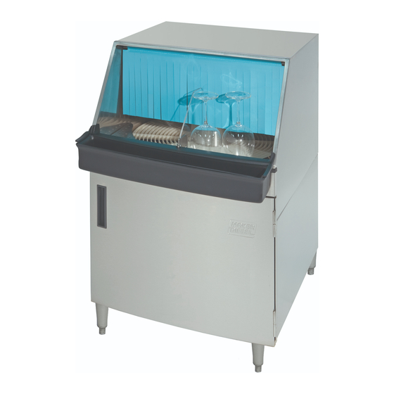
DFM7
(Clockwise Rotation)
P.O. Box 4183
Winston-Salem, NC 27115
336/661-1992 Fax: 336/661-1660
Toll-free: 800.858.4477
2674 N. Service Road, Jordan Station
Ontario, Canada L0R 1S0
905/562-4195 Fax: 905/562-4618
Toll-free: 800.263.5798
Rotary-type
Conveyor Glasswasher
Models:
DFM7 Clockwise Rotation
DFM7-1 Clockwise Rotation
DFM7-2 Counter-Clockwise Rotation
Glasswasher serial no.
Issue Date: 5.26.10
Manual P/N 0512651 rev. E
For machines beginning with S/N G080410261
Printed in the USA
Advertisement
Chapters
Table of Contents

Related Manuals for Moyer Diebel DFM7


Summary of Contents for Moyer Diebel DFM7
- Page 1 Installation Manual with Service Replacement Parts Rotary-type Conveyor Glasswasher Models: DFM7 Clockwise Rotation DFM7-1 Clockwise Rotation DFM7-2 Counter-Clockwise Rotation DFM7 (Clockwise Rotation) Glasswasher serial no. Issue Date: 5.26.10 Manual P/N 0512651 rev. E For machines beginning with S/N G080410261 P.O. Box 4183 2674 N.
- Page 2 The USGBC and the CaGBC Member Logos are trademarks owned by the U.S. Green Building Council and The Canadian Green Building Council, respectively, and are used by permission. The logos signify only that Moyer Diebel is a USGBC member and a CaGBC member;...
- Page 3 USE CANADIAN WARRANTY CARD IN CANADA AND USA WARRANTY CARD IN THE UNITED STATES. NO POSTAGE NECESSARY IF MAILED IN THE UNITED STATES BUSINESS REPLY MAIL FIRST-CLASS MAIL PERMIT NO. 2101 WINSTON-SALEM, NC POSTAGE WILL BE PAID BY ADDRESSEE MOYER DIEBEL PO BOX 4183 WINSTON-SALEM, NC 27119-0981...
- Page 4 WARRANTY REGISTRATION CARD Model Serial # Date of Installation: Company Name: Address: (Street) State or Province Zip Code Telephone #: ( Contact: Installation Company: Address: Telephone #: Contact: This Card Must Be Returned to Validate Machine Warranty: IMPORTANT IMPORTANT WARRANTY REGISTRATION CARD Model Serial # Date of Installation:...
- Page 5 Revison History Revision History The Revision History can contain part number changes, new instructions, or information that were not available at print time. We reserve the right to make changes to this manual without notice and without incurring any liability by making the changes. Glasswasher owners may request a revised manual, at no charge, by calling ...
- Page 6 Dear Owner: Thank you for choosing our glasswasher. We appreciate your business. This manual covers: Model DFM7 Rotary-Type Glasswasher, Clockwise Conveyor Rotation (access door front) Model DFM7-1 Rotary-Type Glasswasher, Clockwise Conveyor Rotation (access door right) Model DFM7-2 Rotary-Type Glasswasher, Clockwise Conveyor Rotation...
-
Page 7: Table Of Contents
DFM7 - Table of Contents Table of Contents Revision Record ......................Limited Warranty ......................DFM7 Rotary-type Conveyor Glasswasher Installation ----------------------------------------------------------------------------------- 1 Unpacking ------------------------------------------------------------------------------------- 1 Utility Connections -------------------------------------------------------------------------- 3 Chemicals ------------------------------------------------------------------------------------- 4 Operation ------------------------------------------------------------------------------------- 6 Cleaning ------------------------------------------------------------------------------------- 9 Troubleshooting ----------------------------------------------------------------------------- 10 Service Replacement Parts -------------------------------------------------------------- 15... -
Page 8: Limited Warranty
DFM7 - Limited Warranty LIMITED WARRANTY Moyer Diebel, (herein referred to as "The Company"), P.O. Box 4149, Winston-Salem, North Carolina 27115, and Champion-Moyer Diebel P.O. Box 301, 2674 N. Service Road, Jordan Station, Canada, L0R 1S0, warrants machines, and parts, as set out below. -
Page 9: Installation
Installation Installation Unpacking Move the glasswasher to its permanent location. Open the door and remove the box marked "LEGS". The box contains (4) 6" [152cm] screw-in legs. These legs are threaded tightly into the base of the machine. Remove (2) 1/2-13 x 2" bolts holding the glasswasher to the pallet. Lift the front door off the bottom hinges and set carefully aside. The illustrations below show one method to install the legs without lifting the glasswasher completely off the pallet. CAUTION! The glasswasher water inlet plumbing and the drain piping extend below the pallet. Use extreme care when moving the glasswasher to prevent damage to the glasswasher plumbing. Boxed Legs Water Drain... - Page 10 Installation Installation (continued) Unpacking (continued) 6. Use 2 people to move the machine in order to install the legs. 7. Have 1 person behind the glasswasher tilt it back as the person in front twists the machine to the right. This makes the front left leg mounting hole accessible. 8. Screw 1 of the legs tightly into place. Repeat this process for the remaining legs. 9. Lift the glasswasher off the pallet, and re-install the front door.. 10. Level the glasswasher front-to-back and side-to-side by adjusting the leg bullet feet in or out. 11. Compare the site utilities with the data plate specifications. If they agree, then proceed with the installation according to the diagrams on the next page. 12. Remove the packing material in the glasswasher and discard, then remove any protective film on the machine. Twist the glasswasher TILT to the right, then to the left. Twist the machine to the right until the front right leg mounting Tilt the machine back to clear hole is accessible.
-
Page 11: Utility Connections
Installation Utility Connections (continued) ATTENTION All utility connections must be performed by qualified people that will follow electric, 6 ft. plumbing, and sanitary codes and regulations. (1.5M) 25" [635] Plan View 27" [686] Hot Water Connection: 6¼" [156] 140-160°F/60-71°C ½" IPS 8¾"... -
Page 12: Chemicals
Installation Installation (continued) Chemicals Glassware cleaning chemicals A qualified chemical supplier should supply liquid detergent, sanitizer and rinse-aid for the glasswasher. The glasswasher manufacturer does not sell glassware washing chemicals. A chemical's formulation and strength vary depending on the chemical supplier; therefore, the specifications given below are approximations only. The glasswasher has 3 built-in chemical dispensing pumps for Detergent - Use a commercial grade non-chlorinated detergent specifically made for glasswashers. The recommended concentration of detergent should be .35% Sanitizer - 2 types of sanitizer may be used. (5.25%) Sodium hypochlorite (chlorine bleach) to provide a minimum concentration of 50 ppm in the final rinse. The 50 ppm concentration must be checked using test strips to make sure the proper concentration is maintained. Iodophor (Iodine formulated with a rinse agent), to provide a minimum concentration of 12.5ppm in the final rinse. The 12.5 ppm concentration must be checked using test strips to make sure the proper concentration is maintained. Rinse-aid Consult your chemical supplier for the proper type of rinse-aid to use in the glasswasher. Installing chemical supply containers and chemical pick-up tubes There is enough space inside the lower compartment to hold 3 one gallon containers for detergent, sanitizer, and rinse-aid. - Page 13 Installation Priming the Chemical Injectors and Approximate Chemical Settings Each chemical injector can be adjusted using its prime button and concentration adjusting screw. These controls are located on the right side of the control box located in the lower compartment of the glasswasher. The white injector rotors are visible through the control box window. Push to prime Rinse-aid Rotor Sanitizer Detergent Turn CW to increase(+) CCW to decrease (-) Chemical Injector Prime and Concentration Controls ALL OF THE CHEMICAL SETTINGS BELOW ARE APPROXIMATIONS. CONSULT A QUALIFIED CHEMICAL REPRESENTATIVE TRAINED IN THE USE OF THE TEST EQUIPMENT REQUIRED FOR TAKING SAMPLES AND PERFORMING ADJUSTMENTS.
-
Page 14: Operation
Operation Flow Diagram The diagram below shows the major components of the DFM7 glasswasher and the flow of water and chemicals during normal operation. - Page 15 Operation Quick Operation Guide The glass washing machine is designed to automatically wash a wide variety of glassware. The glass washer consists of a wash section and rinse section. Glasses rotate on a conveyor through each section. A wash tank in the lower compartment holds heated wash water.
- Page 16 Operation Operation (continued) Assembling the Glasswasher Make sure the power switch is in the OFF position. Install the wash arms and rinse spray arms. The spray arms have locating notches in the end of each arm. Push the spray arm straight into the hub. Do not twist. Install the conveyor assembly as follows: Insert the conveyor into the wash chamber keeping the rear raised.
-
Page 17: Cleaning
Cleaning Cleaning Instructions The cleaning instructions are attached to the inside of glasswasher front door. Daily Cleaning or after 8 hours of Operation: 1. Make sure that any glasses on the conveyor are clean, then remove them from the conveyor. 2. -
Page 18: Troubleshooting
Troubleshooting The following troubleshooting guide can help identify a problem and provide a solution. Inspect your glasswasher before you contact an authorized service representative. Problem Cause(s) Solution(s) Glasswasher will not turn ON. Turn breaker/fuse box ON. Main breaker/fuse box OFF Disconnect fuse blown/breaker Turn breaker/fuse box ON. tripped. Replace fuse/Reset Breaker. Glasswasher ON/OFF switch Flip ON/OFF switch ON. OFF. Power cord unplugged. Plug-in power cord. Remove clean glasses from the Clean glass(es) touching the rinse-side of the glasswasher. conveyor shut-off switch. Reposition the conveyor. Conveyor will not rotate. Conveyor center hub out of position. Conveyor support(s) out of Reposition or replace support(s). position and/or broken. Drive gear out of position. Reposition drive gear. Gear teeth on conveyor worn Replace the conveyor. or broken. Replace drive gear. Gear teeth on drive gear worn or broken. Object jamming the conveyor. Remove object. Conveyor drive motor Authorized service agent may Conveyor will not stop defective. - Page 19 Troubleshooting Problem Cause(s) Solution(s) Splash curtain is missing, Re-install the splash curtain or Water sprays out the front of the positioned incorrectly or damaged. replace the splash curtain. glasswasher. Spray arm(s) are damaged or Replace spray arm(s). missing. Reload glass(es). Glass(es) interferes with splash curtain. Clean the spray arm(s). Clogged spray arm(s) makes water come out in wrong direction. Clean spray arm(s). Poor washing results. Water volume from wash and/or rinse spray arm(s) low. Re-install drain/overflow tube Water level in detergent tank low. in wash tank. Service Agent must adjust water level switch until water level is below top of overflow. Water level float ball stuck or filling Clean float ball, replace if filling with water. with water. Authorized service agent may Water level switch defective. replace switch. Detergent and/or rinse-aid supply Refill chemical supplies. low. Authorized service agent may Wash pump and/or water valve(s) replace wash pump and/or and/or line strainers clogged or...
- Page 20 Troubleshooting Problem Cause(s) Solution(s) Increase thermostat setting to Detergent tank thermostat tem- Water temperature below 145°F/66°C perature setting low. 145°F/66°C in detergent tank. Authorized service agent may Thermostat is defective. replace thermostat. Detergent tank heater is defective. Authorized service agent may replace detergent tank heater. Incoming water temperature is Raise incoming below 140°F/60°C. water temperature to 140°F/60°C. Water leaking under glasswasher. Pump water seal defective. Authorized service agent may replace pump seal. Glasswasher drain line is clogged. Clean drain line. Upper wash compartment drain Clean drain screen. screen is clogged. Detergent tank drain screen is Clean detergent tank drain screen. clogged. Building drain line is clogged. Clean building drain line. Condensation is forming on the Open rinse water mixing valve underside of wash compartment. until temperature of water 70°F/21°C Vacuum breaker at rear of Replace vacuum breaker.
- Page 21 Troubleshooting Problem Cause(s) Solution(s) Incoming water pressure must be Flowing water supply line pres- Water flows into glasswasher 5 PSI/35 kPa on pressure gauge sure measured at the glass- when ON/OFF switch is in located on right-side of glasswasher washer exceeds 95 psi [655 the OFF position. lower compartment kPa]. Authorized service agent may Defective solenoid valve(s). rebuild or replace the solenoid valve(s). Defective AUTO-FILL switch. Service agent replace the switch. Reduce flowing water pressure Chemical(s) are not flowing into Rinse water pressure too high measured at the glasswasher the glasswasher. below 95 psi [655 kPa]. Refill the container(s). Chemical container(s) are empty. Remove the supply line(s) from the Chemical supply line(s) are chemical containers and flush with clogged. warm water. Replace supply line(s) and/or pump Chemical supply and/or pump tube(s). tube(s) are broken. No power to chemical dispens- Authorized service agent may replace ing pump(s).
- Page 22 Blank Page This Page Intentionally Left Blank...
-
Page 23: Service Replacement Parts
Service Replacement Parts Service Replacement Parts Illustration List _____________________________________ Page Base Assembly ...................... 16 Conveyor, Guides, Curtains................... 18 Wash Hubs, Spray Arms .................. 20 Conveyor Stop Switch ................... 22 Drive Motor Assembly.................... 24 Vacuum Breaker Assembly .................. 26 Wash Pump and Piping .................. 28 Inlet Plumbing ...................... 30 Sanitizer Plumbling .................... 32 Detergent Tank Assembly . -
Page 24: Base Assembly
Base Assembly... - Page 25 Base Assembly Item Part Description Qty. 112519 Cap Plug, 1" 0501885 Magnetic Door Catch 0712644 Wash Tank Scrap Screen 0312608 Wash Tank Scrap Screen Handle 0501873 Leg 6" 0712642 Door Assy. 111561 Door Handle 100007 Screw, 1/4-20 X1/2" truss head 0712647 Door Bracket Assy.
-
Page 26: Conveyor, Guides, Curtains
Conveyor, Guides, Curtains... - Page 27 Conveyor, Guides, Curtains Item Qty. Part Description 0312603 Conveyor Hub 0312695 Conveyor Guide Block 0312604 Conveyor Tray 0506886 Drive Gear 0506885 Conveyor 0312610 Curtain Rod (3/8"D x 24"L) 0512549 Curtain...
-
Page 28: Wash Hubs, Spray Arms
Wash Hubs, Spray Arms upper wash spray arm upper rinse spray arm notch in center notch on right DFM7 and DFM7-1 Clockwise conveyor rotation Shown lower rinse spray arm lower wash spray arm notch on left notch in center... - Page 29 * Wash and rinse spray arms have notches to make sure they are installed correctly. The illustration on page 20 is for the clockwise conveyor rotation Models DFM7, and DFM7-1. The DFM7-2 conveyor rotation is counter-clockwise. The location of the wash and rinse spray arms are different than the models mentioned above.
-
Page 30: Conveyor Stop Switch
Conveyor Stop Switch... - Page 31 Conveyor Stop Switch Item Qty. Part Description 0512556 Divider Plate 0501412 Screw 10-32 x 3/8" 0712648 Shut-off Arm Assy. 0512555 Conveyor Shut-off Shaft 0512559 Spring 0512557 Conveyor Shut-off Cam 0510854 Dog-point Screw 1/4-20 x 1/2" 0510493 Carriage Bolt 10-24 x 1/2" 0312605 Switch nut plate 0501379...
-
Page 32: Drive Motor Assembly
Drive Motor Assembly... - Page 33 Drive Motor Assembly Item Qty. Part Description 0506886 Drive Gear 0507264 Water Slinger 0501923 Extension Spring 0512713 Snap Bushing 0501412 Screw 10-32 x 3/8" 0307617 Drive Motor Housing Cover 0512532 Drive Motor 0712712 Drive Motor Housing...
-
Page 34: Vacuum Breaker Assembly
Vacuum Breaker Assembly... - Page 35 Vacuum Breaker Assembly Item Qty. Part Description 0502665 1/2" I.D. Braided Hose 0503679 7/16" Gear Clamp 0502653 3/8" MPT x 1/2" MPT Hose Barb 100500 1/2" Vacuum Breaker 0508366 Vacuum Breaker Repair Kit 0502651 1/2" MPT x 1/2" Hose barb 0312684 Plumbing Support 106026...
-
Page 36: Wash Pump And Piping
Wash Pump and Piping... - Page 37 Wash Pump and Piping Item Qty. Part Description 0512679 Motor Capacitor 6.3uF, 370VAC 0512531 Wash Pump/Motor Assy. Complete 230V/50-60Hz/1Ph 0512678 Pump Kit (Items 4 & 5 are included in the kit) 0512677 Wash Pump Shaft Seal 0512680 Wash Pump Impeller 6"...
-
Page 38: Inlet Plumbing
Inlet Plumbing To Vacuum Breaker To Detergent Tank Cold Water Valve Hot Water Valve Water solenoid detail... - Page 39 Inlet Plumbing Item Part Qty. Description 0502783 Solenoid Valve, 230VAC/60 HZ 0502802 3/8” MPT Tee 0503801 3/8” Fem x 1/2” Adapter 0507324 3/8” Check Valve 0502768 Mixing Valve 0502653 3/8” x 1/2’ 90º Hose Barb 0503679 7/16” Gear Clamp 0502665 1/2”...
-
Page 40: Sanitizer Plumbling
Sanitizer Plumbing... - Page 41 Sanitizer Plumbing Item Qty. Part Description 0502665 1/2" I.D. Braided Hose 0503679 7/16" Gear Clamp 0502663 3/8" I.D. Braided Hose 0502652 1/2" x 1/2" x 3/8" Tee 0503669 Injector Barb Fitting 0501519 Cable Tie 4" 0502666 Chemical Tubing 1/8" IDx1/4"OD 0502653 3/8"...
-
Page 42: Detergent Tank Assembly
Detergent tank Assembly To control box... - Page 43 Detergent tank Assembly Item Qty. Part Description 0312592 Steam Cover 0312591 Detergent Tank Cover 0712641 Detergent Tank Screen 0501395 Set Screw 1/4-20 0312682 Float Cam 0501397 Set Screw 6-40 0703673 Cam Bushing (set screw included) 0512554 Float Rod 0503670 Float Ball 0712640 Detergent Tank 0307427...
-
Page 44: Control Box Assembly
Control Box Assembly To glass washer From chemical container Rinse-aid Sanitizer Detergent... - Page 45 Control Box Assembly Item Qty. Part Description 0501353 Injector Motor, 140RPM 12VDC 0707142 Injector Rotor Assembly 0706635 Element Tube 45CC (DET, SANI) 0706634 Element Tube 15CC (R/A) 0503695 Chemical Tube Detergent Label ------ 0503694 Chemical Tube Sanitizer Label ------ 0505483 Chemical Tube Rinse-aid Label 0306363 Stiffener Tube...
-
Page 46: Options And Accessories
Options And Accessories... - Page 47 Options and Accessories Options and Accessories Item Qty. Part Description 0708986 Tube Scraper 0501826 Tube Brush 0501633 Jet Reamer (comes with Drill) Item Qty. Part Description 0703454 Wash Down Nozzle 0505320 1/2" Hose Washer 0502779 Nozzle 0501833 1/2" x 10' Hose Assy. 0506643 Faucet 0701956...
-
Page 48: Electric Schematic
Electric Schematic... - Page 49 Blank Page This Page Intentionally Left Blank...
Need help?
Do you have a question about the DFM7 and is the answer not in the manual?
Questions and answers