Table of Contents
Advertisement
Quick Links
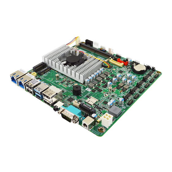
JMTX-ADN1 Series
User's Manual
NO.: G03-MTX-ADN1-F
Revision: 1.0
Release date: February 2, 2024
Trademark:
* Specifications and Information contained in this documentation are furnished for information use only, and are
subject to change at any time without notice, and should not be construed as a commitment by manufacturer.
Advertisement
Table of Contents

Subscribe to Our Youtube Channel
Related Manuals for JETWAY JMTX-ADN1 Series


Summary of Contents for JETWAY JMTX-ADN1 Series
- Page 1 JMTX-ADN1 Series User’s Manual NO.: G03-MTX-ADN1-F Revision: 1.0 Release date: February 2, 2024 Trademark: * Specifications and Information contained in this documentation are furnished for information use only, and are subject to change at any time without notice, and should not be construed as a commitment by manufacturer.
- Page 2 Environmental Protection Announcement Do not dispose this electronic device into the trash while discarding. To minimize pollution and ensure environment protection of mother earth, please recycle.
-
Page 3: Table Of Contents
TABLE OF CONTENT ENVIRONMENTAL SAFETY INSTRUCTION ................iv USER’S NOTICE ........................v MANUAL REVISION INFORMATION ..................v ITEM CHECKLIST ........................v CHAPTER 1 INTRODUCTION OF THE MOTHERBOARD FEATURE OF MOTHERBOARD ................1 SPECIFICATION ......................2 LAYOUT DIAGRAM ....................4 CHAPTER 2 HARDWARE INSTALLATION JUMPER SETTINGS .................... -
Page 4: Environmental Safety Instruction
Environmental Safety Instruction Avoid the dusty, humidity and temperature extremes. Do not place the product in any area where it may become wet. 0 to 60 centigrade is the suitable temperature. (The figure comes from the request of the main chipset) ... -
Page 5: User's Notice
USER’S NOTICE COPYRIGHT OF THIS MANUAL BELONGS TO THE MANUFACTURER. NO PART OF THIS MANUAL, INCLUDING THE PRODUCTS AND SOFTWARE DESCRIBED IN IT MAY BE REPRODUCED, TRANSMITTED OR TRANSLATED INTO ANY LANGUAGE IN ANY FORM OR BY ANY MEANS WITHOUT WRITTEN PERMISSION OF THE MANUFACTURER. -
Page 6: Chapter 1 Introduction Of The Motherboard
Chapter 1 Introduction of the Motherboard 1-1 Feature of Motherboard Onboard Intel® Processor N-series (TDP12W),with low power consumption never denies high performance Support 1* DDR5 4800MHz SO-DIMM, maximum capacity up to 32GB Onboard 2* i226V 2.5GbE LAN port ... -
Page 7: Specification
1-2 Specification Spec Description Design Mini-ITX SBC; PCB size: 17x 17 cm Integrated with Intel Alder Lake-N series CPU ® (TDP 12W) Embedded * Note: CPU model varies from different IPC options. Please consult your dealer for more information of onboard CPU.TDP varies depending on CPU. 1* DDR5 SO-DIMM slot support 1* DDR5 4800MHz up to 32GB ... - Page 8 2* USB2.0 port 1* USB3.2 (Gen.2) Type-A port 1* USB3.2 (Gen.2) Type-C port supports DP1.4a display output 2* HDMI 2.0b 1* Audio Line-out/MIC port 1* Serial port (RS232/422/485, 5V/12V selectable) 1* 12~28V DC-in power Jack (DCIN1) ...
-
Page 9: Layout Diagram
*Note: The main differences among JMTX-ADN1 series are listed as below: TPM2.0 Onboard 64GB eMMC Model JMTX-ADN1-N97000 JMTX-ADN1-N97002 JMTX-ADN1-N97004 JMTX-ADN1-N97008 1-3 Layout Diagram Rear IO Diagram: USB3.2 (Gen.2) Type-A Port 12V~28V (USB1) DC-in Power Jack HDMI2.0b Ports USB 2.0 Ports... - Page 10 Diagram-Front Side: M.2 M-key Slot CPUFAN (M2M1) Flash ROM Update Wafer Connector (REFLASH CON) 2.5Gbps RJ-45 LAN Ports SATAIII Port 1* DDR5 SATA Power Out SODIMM M.2 E-key Slot Connector Slot (M2E1) USB2.0 Ports Front Panel Top: Type-A USB3.2 Header (Gen.2) Port (USB1) Bottom: Type-C USB3.2 (Gen.2)
- Page 11 Jumper Positions: JP11 JP13 JBAT COPEN JP10 JP12 JAT_ATX...
- Page 12 Jumpers Jumper Name Description Pitch ME Features Function Select 2-Pin Block 2.0mm JP13 COM1 Port Pin-9 Function Select 4-Pin Block 2.0mm JP12 COM2 Header Pin-9 Function Select 4-Pin Block 2.0mm COM3 Header Pin-9 Function Select 4-Pin Block 2.0mm JP10 COM4 Header Pin-9 Function Select 4-Pin Block 2.0mm COM5 Header Pin-9 Function Select 4-Pin Block 2.0mm...
- Page 13 Connectors Connector Name RJ-45 LAN Port Connector X2 LAN1/LAN2 USB2.0 Port Connector X2 USB2 USB3.2 (Gen.2) Port Connector USB3 USB3.2 (Gen.2) Type-C Port Connector USB1 *Support ALT Mode HDMI2.0b Port Connector X2 HDMI1_2 Audio Line Out/MIC Combo Connector AUDIO Serial Port (RS232/422/485) Connector COM1 *Support 5V/12V 12~28V DC–in Power Connector...
- Page 14 Headers Header Name Description Pitch BIOS Flash ROM Update Wafer 20-pin Block 1.0mm REFLASH_CON Front Panel Audio Header 9-pin Block 2.0mm FP_AUDIO 3W Amplifier Wafer 4-pin Block 2.0mm SPEAK_CON GPIO Port Header 10-pin Block 2.0mm GPIO RS232 Serial Port Header 9-pin Block 2.0mm COM2/3/4/5/6...
-
Page 15: Jumper Settings
Chapter 2 Hardware Installation 2-1 Jumper Settings JP13 (2-pin): ME Features Function Select (2.0 pitch) JP13 1-2 Open: Enable ME Features (Default); 1-2 Closed: Disable ME Features. JP12 (4-pin): COM1 Port Pin-9 Function Select (2.0 pitch) COM1 JP12 2-4 Closed: 3-4 Closed: 4-6 Closed: RI= +5V;... - Page 16 JP6 (4-pin): COM2 Header Pin-9 Function Select (2.0 pitch) COM2 2-4 Closed: 3-4 Closed: 4-6 Closed: RI=RS232; RI= +5V; RI= +12V. JP10 (4-pin): COM3 Header Pin-9 Function Select (2.0 pitch) JP10 COM3 2-4 Closed: 3-4 Closed: 4-6 Closed: RI= +5V; RI= +12V.
- Page 17 JP9 (4-pin): COM4 Header Pin-9 Function Select (2.0 pitch) COM4 2-4 Closed: 3-4 Closed: 4-6 Closed: RI=RS232; RI= +5V; RI= +12V. JP7 (4-pin): COM5 Header Pin-9 Function Select (2.0 pitch) COM5 2-4 Closed: 3-4 Closed: 4-6 Closed: RI= +5V; RI= +12V. RI=RS232;...
- Page 18 JP8 (4-pin): COM6 Header Pin-9 Function Select (2.0 pitch) 2-4 Closed: 3-4 Closed: 4-6 Closed: RI=RS232; RI= +5V; RI= +12V. COM6 JAT_ATX (3-pin): ATX Mode/AT Mode Select (2.0 pitch) 1-2 Closed: ATX Mode Selected (Default); JAT_ATX 2-3 Closed: AT Mode Selected. *ATX Mode Selected: Press power button to power on after power input ready;...
- Page 19 COPEN (2-pin): Case Open (2.0 pitch) 1-2 Open: Enable ME Features (Default); COPEN 1-2 Closed: Disable ME Features. Pin (1-2) Closed: When Case open function pin short to GND, the Case open function was detected. When used, needs to enter BIOS and enable ‘Case Open Detect’ function. In this case if your case is removed, next time when you restart your computer, a message will be displayed on screen to inform you of this.
- Page 20 JP4 (2-pin): GPIO Header 80 Port/GPIO Function Select (2.0 pitch) 1-2 Open: GPIO_CON =80 Port; 1-2 Closed: GPIO_CON =GPIO Port (Default). JP11 (3-pin): INVERTER1 VCC 5V/12V Select (2.0 pitch) INVERTER1 JP11 1-2 Closed: Inverter VCC=5V (Default); 2-3 Closed: Inverter VCC=12V.
- Page 21 JP3 (4-pin): LVDS VCC 3.3V/5V/12V Select (2.0 pitch) LVDS_EDP 2-4 Closed: 3-4 Closed: 4-6 Closed: LVDS VCC= 3.3V; LVDS VCC= 5V; LVDS VCC= 12V. FP (10-pin): Front Panel Function Select (2.54 pitch) Pin 1 PWRLED+ HDDLED+ PWRLED- HDDLED- PWRBT RSTSW...
-
Page 22: Connectors , Headers & Wafers
Connectors, Headers and Wafers 2-2-1 Rear I/O Panel Connectors Icon Name Function This connector is standard RJ-45 LAN jack for Network connection which 2.5Gbps supports10/100/1000/2500 Mbps Ethernet data RJ-45 LAN Port transfer rate (*Note: 2.5Gbps is only supported with CAT 5e UTP cable). Type-A USB2.0 Port To connect USB keyboard, mouse or other devices compatible with USB 2.0 specification. -
Page 23: Motherboard Internal Connectors
2.5Gbps RJ-45 LAN port LED Signals: ** There are two LED next to the RJ-45 LAN port. Please refer to the table below for LAN port LED indications. B: Speed LED A: Activity/Link LED Status Description Status Description No Link 10/100Mbps connection Blinking Data Activity... - Page 24 (2) CPUFAN (4-pin): CPU FAN Connector CPUFAN *Note: Maximum current limit is 1.5A while using 12V working voltage (3) SATA1 (7-pin): SATAIII Port connector This is a high-speed SATAIII port that supports 6GB/s transfer rate. SATA1 Pin No. Definition...
- Page 25 (4) PWROUT (4-pin): SATA HDD Power-Out Connector (2.54 pitch) PWROUT Warning: Make sure that Pin-1 of compatible SATA Power out connector is inserted into corresponding Pin-1 of SATAPWR connector to avoid possible damage to the board and hard disk driver! (5) SYSFAN1 (4-pin): System FAN Connector (2.54 pitch) Pin1...
-
Page 26: Pin Definition For Headers & Wafers
2-2-3 Pin Definition for Headers & Wafers REFLASH_CON (20-pin): BIOS Flash ROM Update Wafer (1.0 pitch) REFLASH_CON Pin2 Pin20 Pin19 Pin1 Pin Define Pin NO. Pin NO. Pin Define Pin 20 Pin 19 SPSW PCTL- Pin 18 Pin 17 PCH_SYS_RESRT- PCH_RSMRST- Pin 16 Pin 15... - Page 27 FP_AUDIO (9-pin): Front Panel Audio Header (2.0 pitch) This header connects to Front Panel Line-out, MIC-In connector with cable. FP_AUDIO Pin 1 MIC2_L MIC2_R AUDIO_JD LINE_OUT_R MIC_JD SENSE LINE_OUT_JD LINE_OUT_L SPEAK_CON (4-pin): 3W Amplifier Wafer (2.0 pitch) SPEAK_CON Pin1...
- Page 28 GPIO (10-pin): GPIO & 80 Port Header (2.0 pitch) Pin1 JP80P Open: For 80Port Function; GPIO JP80P Closed: Normal 8-bit GPIO *Note: Maximum current limit is 1A while using 5V working voltage COM2/3/4/5/6 (9-pin): RS232 Serial Port Headers (2.0 pitch) Pin1 Pin NO.
- Page 29 PS2KBMS (6-pin): PS/2 Keyboard & Mouse Header (2.0 pitch) Pin1 KB_DATA KB_CLK PS2KBMS MS_CLK MS_DATA *Note: Maximum current limit is 0.5A while using 5V working voltage. SMBUS (5-pin): SM BUS Header (2.0 pitch) Pin1 SMBUS SMBUS_CL SMBUS_DATA SMBUS_ALERT- VCC3 *Note: Maximum current limit is 0.3A while using 5V working voltage.
- Page 30 FP_USB1/FP_USB2 (9-pin): USB 2.0 Port Header (2.0 pitch) FP_USB1 FP_USB2 Pin1 -DATA -DATA +DATA +DATA *Note: Maximum current limit is 1.5A while using 5V working voltage INVERTER1 (8-pin): LVDS Inverter Connector (2.0 pitch) Pin1 INVERTER1 Pin No. Definition LCD_BKLT_EN LCD_BKLT_PWM Backlight VCC Backlight VCC BRTNSS_UP...
- Page 31 LVDS_EDP (30-pin): LVDS Port Header (1.25 pitch) LVDS_EDP Pin30 Pin29 Pin1 Pin2 Pin Define Pin NO. Pin NO. Pin Define LCD_VCC Pin 30 Pin 29 LCD_VCC LCD_VCC Pin 28 Pin 27 LCD_VCC LVDSA_DATAN0 Pin 26 Pin 25 LVDSA_DATAP0 LVDSA_DATAN1 Pin 24 Pin 23 LVDSA_DATAP1 LVDSA_DATAN2...
-
Page 32: Maximum Voltage & Current Limit
2-2-4 Maximum Voltage & Current Limit Below is a list of maximum voltage & Current Limit specification for motherboard interface (including but not limited to slots, connectors and headers) for setup reference: Parts Working Voltage Current Support 900mA USB1 5V/12V 500mA x2 USB2 USB Port... -
Page 33: Chapter 3 Introducing Bios
Chapter 3 Introducing BIOS The BIOS options in this manual are for reference only. Different Notice! configurations may lead to difference in BIOS screen and BIOS screens in manuals are usually the first BIOS version when the board is released and may be different from your purchased motherboard. Users are welcome to download the latest BIOS version form our official website. -
Page 34: Bios Menu Screen
Press <Del> to enter Setup/ Press <F7> to enter Popup Menu. 3-2 BIOS Menu Screen The following diagram show a general BIOS menu screen: Menu Bar General Help Items Current Setting Value Menu Items Function Keys... -
Page 35: Function Keys
3-3 Function Keys In the above BIOS Setup main menu of, you can see several options. We will explain these options step by step in the following pages of this chapter, but let us first see a short description of the function keys you may use here: ... -
Page 36: Memu Bars
3-5 Menu Bars There are six menu bars on top of BIOS screen: To change system basic configuration Main To change system advanced configuration Advanced To change chipset configuration Chipset Password settings Security To change boot settings Boot Save setting, loading and exit options. Save &... -
Page 37: Advanced Menu
System Date Set the date. Please use [Tab] to switch between date elements. System Time Set the time. Please use [Tab] to switch between time elements. 3-7 Advanced Menu Connectivity Configuration ► Press [Enter] to make settings for the following sub-items: CNVi Mode Use this item to this option configures connectivity. - Page 38 CPU Configuration ► Press [Enter] to view current CPU configuration and make settings for the following sub-items: Intel(R) SpeedStep(tm) Use this item to allows more than two frequency ranges to be supported The optional settings: [Disabled]; [Enabled] Turbo Mode Use this item to enable/disable processor turbo mode (requires EMTTM enabled too).
- Page 39 When set as [Enabled], the following sub-items shall appear: Active PCR Banks Available PCR Banks SHA256 PCR Bank Use this item to enable or disable SHA256 PCR Bank The optional settings are: [Disabled]; [Enabled] SHA384 PCR Bank Use this item to enable or disable SHA384 PCR Bank The optional settings are: [Disabled];...
- Page 40 Press [Enter] to make settings for the following sub-items: Wake-up System with Fixed Time Use this item to enable or disable system wake on alarm event. The optional settings: [Disabled]; [Enabled]. When set as [Enabled], system will wake on the hour/min/sec specified. Wake-up Hour Use this item to 0-23.
- Page 41 The optional settings: [Disabled]; [Enabled]. USB S5 Power Use this item to USB power after system shutdown support only disable ERP function. The optional settings: [Disabled]; [Enabled] Super I/O Configuration ► Press [Enter] to make settings for the following sub-items: Super IO Configuration ERP Support Use this item to energy-related products function.
- Page 42 Press [Enter] to make settings for the following sub-items: Serial Port Use this item to enable or disable serial port (COM). The optional settings are: [Disabled]; [Enabled]. When set as [Enabled], the following sub-items shall appear: Device Settings Change Settings Use this item to select an optimal setting for super IO device.
- Page 43 Use this item to select an optimal setting for super IO device. The optional settings are: [IO=2E8h; IRQ=10]; [IO=3F8h; IRQ=3,4,5,7,10,11]; [IO=2F8h; IRQ=3,4,5,7,10,11]; [IO=3E8h; IRQ=3,4,5,7,10,11]; [IO=2E8h; IRQ=3,4,5,7,10,11]; [IO=3E0h; IRQ=3,4,5,7,10,11]; [IO=2E0h; IRQ=3,4,5,7,10,11] Serial Port 5 Configuration Press [Enter] to make settings for the following items: Serial Port Use this item to enable or disable serial port (COM).
- Page 44 WatchDog Reset Timer Value User can select a value in the range of [10] to [255] seconds when ‘WatchDog Reset Timer Unit’ set as [Sec]; or in the range of [1] to [255] minutes when ‘WatchDog Reset Timer Unit’ set as [Min]. WatchDog Reset Timer Unit The optional settings are: [Sec.];...
- Page 45 above this pre-set duty. CPUFAN1 Idle-Speed Temperature Use this item to set CPUFAN1 idle speed temperature. Fan will run at idle speed when below this pre-set temperature. CPUFAN1 Idle-Speed Duty Use this item to set CPUFAN1 idle speed duty. Fan will run at idle speed when below this pre-set duty SYSFAN1 Smart Mode The optional settings are: [Disabled];...
- Page 46 compatible settings. Press [Enter] to make settings for the following items: COM1 Console Redirection Settings Terminal Type The optional settings: [VT100]; [VT100Plus]; [VT-UTF8]; [ANSI]. Emulation: ANSI: Extended ASCII char set. VT100:ASCII char set. VT100Plus: Extends VT100 to support color. function keys, etc.; VT-UTF8: Uses UTF8 encoding to map Unicode chars onto 1 or more bytes Bits per second Use this item to select serial port transmission speed.
- Page 47 The optional settings: [None]; [Hardware RTS/CTS]. VT-UTF8 Combo Key Support Use this item to enable VT-UTF8 Combination Key Support for ANSI/VT100 terminals. The optional settings: [Disabled]; [Enabled]. Recorder Mode With this mode enable only text will be sent. This is to capture Terminal data. The optional settings: [Disabled];...
- Page 48 the user is using) will exchange data. Both computers should have the same or compatible settings. Press [Enter] to make settings for the following items: Out-of-Band Mgmt Port The optional setting is: [COM1]. Terminal Type The optional settings: [VT100]; [VT100Plus]; [VT-UTF8]; [ANSI]. VT-UTF8 is the preferred terminal type for out-of-band management.
- Page 49 USB Configuration XHCI Hand-off This is a workaround for OSes without XHCI hand-off support. The XHCI ownership change should be claimed by XHCI driver. The optional settings are: [Enabled]; [Disabled]. USB Mass Storage Driver Support The optional settings are: [Disabled]; [Enabled]. USB Hardware Delays and Time-outs: USB Transfer Time-out Use this item to set the time-out value for control, bulk, and interrupt transfers.
- Page 50 Use this item to enable Ipv4 PXE Boot Support. When set as [Disabled], Ipv4 boot optional will not be created. Ipv6 PXE Support The optional settings are: [Disabled]; [Enabled]. Use this item to enable Ipv6 PXE Boot Support. When set as [Disabled], Ipv6 boot optional will not be created.
-
Page 51: Chipset Menu
3-8 Chipset Menu System Agent (SA) Configuration Press [Enter] to make settings for the following sub-items: ► Maximum Memory Frequency Use this item to Maximum Memory Frequency selections in Mhz The optional settings are: [Auto]; [3200]; [3467]; [3600]; [3733]; [4000]; [4200]; [4267];... - Page 52 DVMT Pre-Allocated Use this item to select DVMT 5.0 Pre-Allocated (Fixed) graphics memory size used by the internal graphics device. The optional settings are: [OM]; [32M]; [64M]; [96M]; [128M]; [160M]; [4M]; [8M]; [12M]; [16M]; [20M]; [24M]; [28M]; [32M/F7]; [36M]; [40M]; [44M]; [48M]; [52M]; [56M];...
-
Page 53: Security Menu
The optional settings: [Disabled]; [Enabled]. HD Audio This item controls detection of the HD-Audio device. The optional settings are: [Disabled]; [Enabled]. [Disabled]: HDA will be unconditionally disabled. [Enabled]: HAD will be unconditionally enabled. eMMC Controller(Option) Use this item to enable or disable eMMC controller The optional settings are: [Disabled];... - Page 54 Security menu allow users to change administrator password and user password settings. Administrator Password If there is no password present on system, please press [Enter] to create new administrator password. If password is present on system, please press [Enter] to verify old password then to clear/change password.
- Page 55 This item enables expert users to modify Secure Boot Policy variables without full authentication. Press [Enter] to make settings for the following sub-items: Factory Key Provision This item is for user to install factory default secure boot keys after the platform reset and while the system is in Setup mode.
-
Page 56: Boot Menu
Key Source: Factory, External, Mixed. 3-10 Boot Menu Setup Prompt Timeout Use this item to set number of seconds to wait for setup activation key. Bootup Numlock State Use this item to select keyboard numlock state. The optional settings are: [On]; [Off]. Quiet Boot The optional settings are: [Disabled];... -
Page 57: Save & Exit Menu
3-11 Save & Exit Menu Save Changes and Reset This item allows user to reset the system after saving the changes. Discard Changes and Reset This item allows user to reset the system without saving any changes. Restore Defaults Use this item to restore /load default values for all the setup options. Save as User Defaults Use this item to save the changes done so far as user defaults. - Page 58 The available options here are dynamically updated and make system boot to any boot option selected. UEFI: Built-in EFI Shell Use this item to launch EFI shell application (shell.efi) from one of the available filesystem device.
Need help?
Do you have a question about the JMTX-ADN1 Series and is the answer not in the manual?
Questions and answers