Table of Contents
Advertisement
Quick Links
3D-AGP VGA / 3D-Audio M/B
FOR Pentium
The author assumes no responsibility for any errors or omissions which
may appear in this document nor does it make a commitment to update
the information contained herein.
Trademark:
*
Pentium is registered trademark and MMX is a trademark of Intel corporation,
the other names and brands are the property of their respective owners.
* Specifications and Information contained in this documentation are furnished for information use only, and are
subject to change at any time without notice, and should not be construed as a commitment by manufacturer.
J-530BF
USER'S MANUAL
NO. G03-530BFRAA
Release date: SEP 2000
** Year 2000 compliant **
®
processor
Advertisement
Table of Contents

Subscribe to Our Youtube Channel
Related Manuals for JETWAY J-530BF


Summary of Contents for JETWAY J-530BF
- Page 1 J-530BF USER'S MANUAL 3D-AGP VGA / 3D-Audio M/B ® FOR Pentium processor The author assumes no responsibility for any errors or omissions which may appear in this document nor does it make a commitment to update the information contained herein.
-
Page 2: Table Of Contents
TABLE OF CONTENT Chapter 1 1-1 Preface ....................1 1-2 Key Feature ...................1 Chapter 2 Hardware Installation ..................3 2-1 Unpacking....................3 2-2 Mainboard Layout .................4 2-3 Quick Reference for Jumpers, Connectors & Expansion Socket ..5 2-4 Installation Steps ..................6 2-5 Jumper Settings..................6 2-6 System Memory (DRAM) ..............8 2-7 Central Processing Unit (CPU) ............9 2-8 Expansion Cards...................9... -
Page 3: Preface
This mainboard is based on Pentium ® Welcome to use the J-530BF processor PC/AT compatible system with ISA bus and PCI local bus. Also for this board including some special designs like, support 100MHz frequency, 3D AGP VGA chip, 3D PCI Audio chip, ACPI/AMP power management &... - Page 4 • ISA and PCI ecpansion Slots: Privodes two 16-bit ISA slots, three PCI slots. • Super Multi-I/O: Provides two high-Speed UART compatible serial ports and one parallel port with EPP and ECP capabilities. UART2 can also be directed to the Infrared Module for wireless connections.
-
Page 5: Hardware Installation
Chapter 2 Hardware Installation 2-1 Unpacking This mainboard package should contain the following: • J-530BF mainboard • USER’S MANUAL for mainboard • Cable set for IDE x1, Floppy x1, COM1 & COM2 x1, LPT & PS/2 Mouse x1, VGA x1,Audiox1 •... -
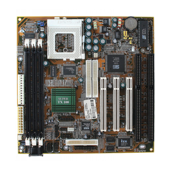
Page 6: Mainboard Layout
2-2 Mainboard Layout SYSFAN1 AT PO WE R C O NN. ATX PO WE R CO NN. DIMM3 DIMM2 DIMM1 CO M1 C O M2 32K X 8 ES1938S JP13 USB1 IDE 2 IDE 1 C PUFAN1 PC I 1 5595 PC I 2 BATT. -
Page 7: Quick Reference For Jumpers, Connectors & Expansion Socket
Expansion Socket Jumpers Jumper Name Description Page CMOS RAM Clear 2-3 Normal ,1-2 Clear CMOS p. 8 CPU Voltage selector for detail page 7 p. 6 JP2,JP3 Jumpers for CPU type selection for detail page 7 p. 6 Connectors Connector Name Description Page... -
Page 8: Jumper Settings
Before using your computer, you must follow the steps as follows: 1. Set Jumpers on the Motherboard 2. Install the CPU 3. Install DRAM Modules 4. Install Expansion card 5. Connect Cables, Wires, and Power Supply 2-5 Jumper Settings 1. CPU Voltage Selection: JP8 (2x5pin Block) This jumper is used for adjusting CPU working voltage, for this main board design it can auto detect the single voltage CPU or dual voltage CPU. - Page 9 66.8 MHz 66.8 MHz 75 MHz 75 MHz 83.3 MHz 83 MHz 95 MHz 95 MHz 100 MHz 100 MHz 112 MHz 112 MHz 90/66.8 MHz 90/89 MHz 83.3 MHz 66.8 MHz 95 MHz 63.3 MHz 100 MHz 66.6 MHz 100/105 MHz 75 MHz 112 MHz...
-
Page 10: System Memory (Dram)
NOTE: Before installing the CPU, Please check the CPU Frequency and Clock Ratio from your supplier. For Cyrix/IBM 6X86MX series, please double check the CPU’s Frequency and Clock Ratio. 3. CMOS RAM Clear: JP6 (Yellow color selector) WARNING: Make sure your computer is POWER OFF when you CLEAR CMOS. Connect a jumper Cap over this jumper for a few seconds, will clears information stored in the CMOS RAM Chip that input by user, such as hard disk information and passwords. -
Page 11: Central Processing Unit (Cpu)
2-7 Central Processing Unit (CPU) The main board provides a 321-pins ZIF Socket 7. The CPU on mother board must have a fan attached to prevent overheating. WARNING: Without a fan, the CPU will be overheated and cause damage to both the CPU and the motherboard. - Page 12 Using a slight angle, align the plastic guide pins on the lead to their receptacles on the connector. Once aligned, press the lead onto the connector until the lead locks into place. +12V -12V Power Connector on Motherboard Power Plugs from Power Supply 2.
- Page 13 5. Parallel Printer Connector (26-pin Block): LPT1 Connection for the enclosed parallel port ribbon cable with mounting bracket. Connect the ribbon cable to this connection and mount the bracket to the case on an open slot. It will then be available for a parallel printer cable. NOTE: Serial printers must be connected to the serial port.
- Page 14 Pin 1 Primary IDE Connector Secondary IDE Connector (40-pin block): IDE2 This connector connects to the next set of Master and Slave hard disks. Follow the same procedure described for the primary IDE connector. You may also configure two hard disks to be both Masters using one ribbon cable on the primary IDE connector and another ribbon cable on the secondary IDE connector.
- Page 15 Turbo SW/ Power LE D/ Keyboard AC PI LE D Lock VC C G ND VC C G ND G ND G ND G ND VC C G ND R eset Turbo Speaker LE D System Case Connections 12. IR infrared module connector: IR1 This connector supports the optional wireless transmitting and receiving infrared module.
- Page 16 PS-O N ATX Power button/Soft Power button 16. VGA connector: VGA1 This connector supports the provided VGA cable with mounting bracket. Connect the ribbon cable to connector and mount the bracket to the case on an open slot . Orient the red stripe on the monitor cable with Pin 1 VG A1 VGA Connector...
- Page 17 20. Wake On Lan connector: WOL WO N +5VSB G ND W O N 21. On Board Audio chip Enbled / Disabled connector: JP13 JP13 Closed (Default) : Enabled Open (Default) : Disabled 22. SB_Link connector: J5 G ND PCREQ* SIRQ PCG NT* NC G ND Audio Connector...
-
Page 18: Chapter 3 Award Bios Setup
Chapter 3 AWARD BIOS SETUP Award's ROM BIOS provides a built-in Setup program which allows user modify the basic system configuration and hardware parameters. The modified data will be stored in a battery-backed CMOS RAM so data will be retained even when the power is turned off. In general, the information saved in the CMOS RAM stay unchanged unless here is configuration change in the system, such as hard drive replacement or new equipment is installed. -
Page 19: Standard Cmos Setup
3-1 STANDARD CMOS SETUP Choose "STANDARD CMOS SETUP" in the CMOS SETUP UTILITY Menu (Figure 3-1). The STANDARD CMOS SETUP allows user to configure system setting such as current date and time, type of hard disk drive installed in the system, floppy drive type, and the type of display monitor. -
Page 20: Bios Features Setup
3-2 BIOS FEATURES SETUP Select the "BIOS FEATURES SETUP" option in the CMOS SETUP UTILITY menu allows user to change system related parameters in the displayed menu. This menu shows all of the manufacturer's default values of this motherboard. Again, user can move the cursor by pressing direction keys and <PgDn>... - Page 21 Disabled: No warning message to appear when anything attempts to access the boot sector or hard disk partition table. • CPU Internal Cache / External Cache: These two categories speed up memory access. However, it depends on CPU/chipset design. The default value is Enable. If your CPU without Internal Cache then this item "CPU Internal Cache"...
- Page 22 Disabled: Disable typematic rate and typematic delay programming. The system BIOS will use default value of this 2 items and the default is controlled by keyboard. • Typematic Rate (Chars/Sec): 6 : 6 characters per second : 8 characters per second 10 : 10 characters per second 12 : 12 characters per second 15 : 15 characters per second...
-
Page 23: Chipset Features Setup
3-3 CHIPSET FEATURES SETUP This section allows you to configure the system based on the specific features of the installed chipset. This chipset manages bus speeds and access to system memory resources, such as DRAM and the external cache. It also coordinates communications between the conventional ISA bus and the PCI bus. - Page 24 The choice: 3.9us, 7.8us, 15.6us. • Ref / Act Command Delay: Set the DRAM clock of the refresh command to refresh/active command delay. The choice: 5T, 6T, 7T, 8T. • Refresh Queue Depth: Set the depth of refresh queue. The choice: 0, 4, 8, 12. •...
- Page 25 • PCI Peer Concurrency : Peer concurrency means that more than one PCI device can be active at a time. The choice: Enabled, Disabled. • Read Prefetch Memory RD : When this item is Enabled, the system is allowed to prefetch the next read instruction and initiate the next process.
-
Page 26: Power Management Setup
• DRAM Controller 1 T WR/RD : Enable/disable DRAM controller one cycle write/read for VUMA function. The choice: Enabled, Disabled. • PCI Post Write Buffer : Enable/disable PCI post write buffer. The choice: Enabled, Disabled. • PCI Delayed Transaction : The chipset has an embedded 32-bit posted write buffer to support delay transactions cycles. - Page 27 • Switch Function : You can choose whether or not to permit your system to enter complete Suspend mode. Suspend mode offers greater power savings, with a correspondingly longer awakening period. • Doze Speed (div by): Sets the CPU's speed during Doze mode. The speed is reduced to a fraction of the CPU's normal speed.
-
Page 28: The Description Of The Power Management
Time Clock) so it does not awaken the system from Suspend mode. • Power Button Over Ride : You could press the power button for more than 4 seconds forces the system to enter the Soft-Off state when the system has “hung.” The choice: Instant-Off, Delay 4 Sec. - Page 29 Always On Monitor will remain on during power saving modes. Suspend --> Off Monitor blanked when the systems enters the Suspend mode. Susp,Stby --> Off Monitor blanked when the system enters either Suspend or Standby modes. All Modes --> Off Monitor blanked when the system enters any power saving mode.
-
Page 30: Description Of The Green Function
The choice: Enabled, Disabled. 3-4-2 Description of the Green Functions This motherboard supports HDD Power Down, Doze and standby power saving functions when Intel Pentium processor CPU is installed. The detail description of these functions are provided as following: HDD Standby Mode When system stop reading or writing HDD, the timer starts to count. -
Page 31: Pnp/Pci Configuration Setup
3-5 PNP/PCI CONFIGURATION SETUP This section describes configuring the PCI bus system. PCI, or Personal Computer Interconnect, is a system which allows I/O devices to operate at speeds nearing the speed the CPU itself uses when communicating with its own special components. This section covers some very technical items and it is strongly recommended that only experienced users should make any changes to the default settings. -
Page 32: Load Bios Defaults
Legacy ISA Devices compliant with the original PC AT bus specification, requiring a specific interrupt ( such as IRQ4 for serial port 1). PCI/ISA PnP Devices compliant with the Plug and Play standard, whether designed for PCI or ISA bus architecture. The choice: Legacy ISA, PCI/ISA PnP. -
Page 33: Load Setup Defaults
Esc : QUIT ↑↓→← : Select Item F10 : Save & Exit Setup (Shift) F2 : Change Color Time, Date, Hard Disk Type... Figure 3-7 3-7 LOAD SETUP DEFAULTS The "LOAD SETUP DEFAULTS" function loads the system default data directly from ROM and initialize associated hardware properly. - Page 34 Esc: Quit ↑↓→←: Select Item Onboard FDC Controller : Enabled F1 : Help Pu/Pd/+/-:Modify Onboard Seriel Port 1 : 3F8/IRQ4 F5 : Old Values (Shift)F2 : Color Onboard Seriel Port 2 : 2F8/IRQ3 F6 : Load BIOS Defaults IR Address Select : Disabled F7 : Load Setup Defaults Onboard Parallel Port...
-
Page 35: Supervisor/User Password
• IR Function Duplex: This item allows you to select the IR function when your select the UART2 Mode is ASKIR. Choices are Half , Full. • RxD,TxD Active : This item allows you to determine the active of RxD,TxD. Choices are “Hi,Hi”... -
Page 36: Ide Hdd Auto Detection
3. After you enter the password, the following message appears prompting you to confirm the password: “Confirm Password:” 4. Enter exact the same password you just typed again to confirm the password and press <Enter>. 5. Move the cursor to Save & Exit Setup to save the password. 6. -
Page 37: Save & Exit Setup
no. Cylinder (1024) no. Head no. Sector no. per sector ( 512) 528 Megabytes If user set this HDD to NORMAL mode, the maximum accessible HDD size will be 528 Megabytes even though its physical size may be greater than that! LBA (Logical Block Addressing) mode A new HDD accessing method to overcome the 528 Megabyte bottleneck. -
Page 38: I/O & Memory Map
The "SAVE & EXIT SETUP" option will bring you back to boot up procedure with all the changes you just made which are recorded in the CMOS RAM. 3-12 EXIT WITHOUT SAVING The "EXIT WITHOUT SAVING" option will bring you back to normal boot up procedure without saving any data into CMOS RAM. -
Page 39: Time & Dma Channels Map
360-36F NETWORK ports 378-37F PARALLEL port 1 3B0-3BF MONOCHROME & PARALLEL port adapter 3C0-3CF EGA adapter 3D0-CDF CGA adapter 3F0-3F7 FLOPPY DISK controller 3F8-3FF SERIAL port-1 3-14 TIME & DMA CHANNELS MAP TIME MAP: TIMER Channel 0 System timer interrupt TIMER Channel 1 DRAM REFRESH request TIMER Channel 2 SPEAKER tone generator DMA Channel 0 Available... -
Page 40: Bios Reference-Post Codes
Minutes Minutes alarm Hours Hours alarm Day of week Day of month Month Year Status register A Status register B Status register C Status register D Diagnostic status byte Shutdown byte FLOPPY DISK drive type byte Reserve HARD DISK type byte Reserve Equipment type Base memory low byte... - Page 41 Disable NMI, PIE, AIE, UEI, SOWV. Initialize Chips Disable video, parity checking, DMA. Reset math coprocessor. Clear all page registers, CMOS shutdown byte. Initialize timer 0, 1, and 2, including set EISA timer to a known state. Initialize DMA Controllers 0 and 1. Initialize interrupt controllers 0 and 1.
- Page 42 BIOS checksum test. Test DMA Controller 0 Keyboard detect and initialization. Test DMA Controller 1 Test DMA Page Registers Test DMA Page Registers. 12-13 Reserved Test Timer Counter 2 Test 8254 Timer 0 Counter 2. Test 8259-1 Mask Bits Verify 8259 Channel 1 masked interrupts by alternately turning off and on the interrupt lines.
- Page 43 Display virus protest disable or enable. Initialize Floppy Initialize floppy disk drive controller and drives. Drive & Controller Initialize Hard Drive & Initialize hard drive controller and any drives. controller Detect & Initialize Initialize any serial and parallel ports (also game port). Serial/Parallel Ports Reserved Detect &...
-
Page 44: Sound Card Driver Quick Installation
Chapter 4 Software Installed 4-1 Sound Card Driver Quick Installation: Windows 95 OSR2 Driver Installation step1: Before install sound driver please double-click ”My Computer” icon, ”Control Panel”icon, ”System”icon,”Device Manager”icon step2: check”Other device”item,if there have”PCI Multimedia Audio Device”,please remove it first. step3: In ”Control Panel”... -
Page 45: Display Card Driver Quick Installation
step6: When Windows98 ask ”Are all your drivers installed now” Please select ”Yes” and click ”Next”, ”Finish” . step7: Restart System. JOYSTICK Installation In Windows95 OSR2, Windows98,double-click ”My Computer”, ”Game controllers”,select ”Properties” item, ”Cailibrate” to adjust your joystick before using it. 4-2 Display Card Driver Quick Installation WINDOWS 95/98 Display Driver Quick Installation Step 1. - Page 46 step2: Selet “Next” to complete install driver. step3: The program will automatic install driver to system if users have question in system Hardware Monitor Setting, please read “HELP” Section in program.
Need help?
Do you have a question about the J-530BF and is the answer not in the manual?
Questions and answers