Table of Contents
Advertisement
Quick Links
Chapter 1
1-1 Preface ...........................................................................................
1-2 Key Feature ....................................................................................
Chapter 2
..........................................................................................
2-1 Unpacking ................................................................................
2-2 Mainboard Layout ...................................................................
2-3 Installation Steps.....................................................................
2-4 Central processing Unit (CPU) ..............................................
2-5 Expansion Cards .....................................................................
2-6 External Connectors ................................................................
Chapter 3
3-1 STANDARD CMOS SETUP ............................................................... 17
3-2 BIOS FEATURES SETUP .................................................................. 18
3-3 CHIPSET FEATURES SETUP ........................................................... 21
3-4 POWER MANAGEMENT SETUP ...................................................... 24
3-4-1 The Description of the Power Management......................... 26
3-4-2 Description of the Green Functions ..................................... 28
3-5 PNP/PCI CONFIGURATION SETUP ................................................. 29
3-6 LOAD BIOS DEFAULTS .................................................................... 30
3-7 LOAD SETUP DEFAULTS................................................................. 31
3-8 INTEGRATED PERIPHERALS SETUP ............................................. 31
3-9 SUPERVISOR/USER PASSWORD ................................................... 33
3-10 IDE HDD AUTO DETECTION .......................................................... 34
3-11 SAVE & EXIT SETUP....................................................................... 35
3-12 EXIT WITHOUT SAVING ................................................................. 35
3-13 I/O & MEMORY MAP ....................................................................... 36
3-14 TIME & DMA CHANNELS MAP....................................................... 37
3-15 INTERRUPT MAP ............................................................................ 37
3-16 RTC & CMOS RAM MAP ................................................................. 37
3-17 BIOS REFERENCE-POST CODES ................................................. 38
Chapter 4
4-1 Sound Card Driver Quick Installation ......................................................42
4-2 Display Card Driver Quick Installation.....................................................43
4-2 PC HEALTH MONITOR-II SOFTWARE..................................................43
TABLE OF CONTENT
................................................................
..................................................
....................................................................... 16
i
1
1
3
3
4
6
6
8
9
9
10
Advertisement
Table of Contents

Related Manuals for JETWAY J-Mark J-530CF


Summary of Contents for JETWAY J-Mark J-530CF
-
Page 1: Table Of Contents
TABLE OF CONTENT Chapter 1 1-1 Preface ................... 1-2 Key Feature ..................Chapter 2 Installation ..................2-1 Unpacking ................2-2 Mainboard Layout ..............2-3 Installation Steps............................. 2-3-1 Jumper Settings ..........2-3-2 System Memory (DRAM) 2-4 Central processing Unit (CPU) ..........2-5 Expansion Cards .............. -
Page 2: Preface
Chapter 1 1-1 Preface mainboard. This mainboard is based on Pentium ® processor Welcome to use the J-530CF PC/AT compatible system with ISA bus and PCI local bus. Also for this board including some special designs like, support 100MHz frequency, 3D AGP VGA chip , 3D PCI Audio chip, ACPI/AMP power management &... - Page 3 • DRAM Memory Support: support 3 168-pin DIMMS(3.3V)from a memory size befween 8MB to 768MB. • ISA and PCI ecpansion Slots: Privodes two 16-bit ISA slots, three PCI slots. • Super Multi-I/O: Provides two high-Speed UART compatible serial ports and one parallel port with EPP and ECP capabilities.
-
Page 4: Installation
Chapter 2 Hardware Installation 2-1 Unpacking This mainboard package should contain the following: • J-530CF mainboard • USER’S MANUAL for mainboard • Cable set for IDE x1, Floppy x1,COM x1 • CD for Drivers PACK The mainboard contains sensitive electronic components which can be easily damaged by electron-static, so the mainboard should be left in its original packing until it is installed. -
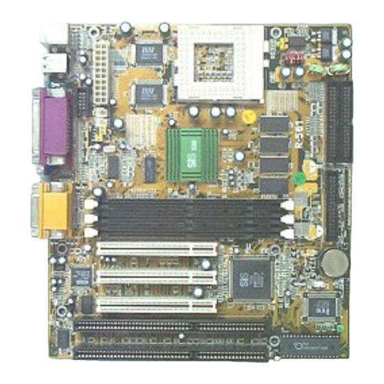
Page 5: Mainboard Layout
2-2 Mainboard Layout 64KX64 C O M1 64KX64 SYSFAN1 CPUFAN1 LPT1 VG A1 DIMM1 DIMM2 DIMM3 PC I 1 BATT. PC I 2 5595 IR 1 PC I 3 ISA1 ITE 8661F ISA2 BIO S Figure 2-1... - Page 6 Jumpers 1) SW1,JP2 p. 6 Jumpers for CPU type selection p. 8 CMOS RAM (Normal/Clear CMOS Data) (Yellow Color selector) p. 6 CPU Voltage selector Connectors 1) PW1 p. 10 ATX Power connector (20-pin Block) 2) KBMS1 p. 10 PS/2 Mouse & PS/2 Keyboard connector(6-pin Female) 3) LPT1 p.
-
Page 7: Installation Steps
2-3 Installation Steps Before using your computer, you must follow the steps as follows: 1. Set Jumpers on the Motherboard 2. Install the CPU 3. Install DRAM Modules 4. Install Expansion card 5. Connect Cables, Wires, and Power Supply 2-3-1 Jumper Settings CPU Voltage Selection: JP3 (2x5pin Block) This jumper is used for adjusting CPU working voltage, for this main board design it can auto detect the single voltage CPU or dual voltage CPU. - Page 8 CPU Bus Clock SDRAM Clock 66.8 MHz 66.8 MHz 75 MHz 75 MHz 83.3 MHz 83 MHz 95 MHz 95 MHz 100 MHz 100 MHz 112 MHz 112 MHz 66.8 MHz 89 MHz * 83.3 MHz 66.8 MHz * 95 MHz 63.3 MHz * 100 MHz 66.6 MHz *...
-
Page 9: System Memory (Dram)
NOTE: 1. Before installing the CPU, Please check the CPU Frequency and Clock Ratio from your supplier. 2. For Cyrix/IBM 6X86MX series, please double check the CPU’s Frequency and Clock Ratio. 1. CMOS RAM: JP7 (Yellow color selector) WARNING: Make sure your computer is POWER OFF when you are CLEAR CMOS. Connect a jumper Cap over this jumper for a few seconds, will clears information stored in the CMOS RAM Chip that input by user, such as hard disk information and passwords. -
Page 10: Central Processing Unit (Cpu)
2-4 Central Processing Unit (CPU) The main board provides a 321-pins ZIF Socket 7. The CPU on mother board must have a fan attached to prevent overheating. WARNING: Without a fan, the CPU will be overheated and cause damage to both the CPU and the motherboard. -
Page 11: External Connectors
2-6 External Connectors 1. ATX Power Connector (20-pins block): PW1 ATX Power Supply connector. This is a new defined 20-pin connector that usually comes with ATX case. The ATX Power Supply allows to use soft power on momentary switch that connect from the front panel switch to 2-pin Power On jumper pole on the motherboard. - Page 12 4. Serial Port COM1 and VGA Connector: COM1, VGA1 COM1 is the 9-pin D-Subminature mail connector. VGA1 is the 15-pin D-Subminature Recepfacle connector.The On-board serial port can be disabled through BIOS SETUP. Please refer to Chapter 3 “INTEGRATED PERIPHERALS SETUP“ section for more detail information.
- Page 13 Floppy drive Connector (34-pins block): FDD(FLOPPY CONN) This connector supports the provided floppy drive ribbon cable. After connecting the single plug end to motherboard, connect the two plugs at other end to the floppy drives. Pin 1 Floppy Drive Connector Primary IDE Connector (40-pins block): IDE1 This connector supports the provided IDE hard disk ribbon cable.
- Page 14 Pin 1 Secondary IDE Connector 10. IDE activity LED: HDLED (SMI S/W 1&3) This connector connects to the hard disk activity indicator light on the case. IDE (Hard Drive) LED 11. Turbo LED switch: TBLED The motherboard‘s turbo function is always on. The turbo LED will remain constantly lit while the system power is on.
- Page 15 This connector supports the optional wireless transmitting and receiving infrared module. This module mounts to small opening on system cases that support this feature you must also configure the setting through BIOS setup. Use the four pins as shown on the Back View and connect a ribbon cable from the module to the motherboard according to the pin definitions.
- Page 16 PS-ON Push Button Power-On button connector 20. CD Audio in connector : J2,J3 These two connectors are design for two type of CD-ROM output cable. Sony Compatible Panasonic Compatible CD-ROM Audio connector 21. On board sound chip Enbled / Disabled connector connector : JP9 Closed (Default) : Enabled Open : Disabled 22.
-
Page 17: Award Bios Setup
Chapter 3 AWARD BIOS SETUP Award's ROM BIOS provides a built-in Setup program which allows user modify the basic system configuration and hardware parameters. The modified data will be stored in a battery-backed CMOS RAM so data will be retained even when the power is turned off. In general, the information saved in the CMOS RAM stay unchanged unless here is configuration change in the system, such as hard drive replacement or new equipment is installed. -
Page 18: Standard Cmos Setup
3-1 STANDARD CMOS SETUP Choose "STANDARD CMOS SETUP" in the CMOS SETUP UTILITY Menu (Figure 3-1). The STANDARD CMOS SETUP allows user to configure system setting such as current date and time, type of hard disk drive installed in the system, floppy drive type, and the type of display monitor. -
Page 19: Bios Features Setup
3-2 BIOS FEATURES SETUP Select the "BIOS FEATURES SETUP" option in the CMOS SETUP UTILITY menu allows user to change system related parameters in the displayed menu. This menu shows all of the manufacturer's default values of this motherboard. Again, user can move the cursor by pressing direction keys and <PgDn>... - Page 20 Disabled: No warning message to appear when anything attempts to access the boot sector or hard disk partition table. • CPU Internal Cache / External Cache: These two categories speed up memory access. However, it depends on CPU/chipset design. The default value is Enable. If your CPU without Internal Cache then this item "CPU Internal Cache"...
- Page 21 Disabled: Disable typematic rate and typematic delay programming. The system BIOS will use default value of this 2 items and the default is controlled by keyboard. • Typematic Rate (Chars/Sec): 6 : 6 characters per second : 8 characters per second 10 : 10 characters per second 12 : 12 characters per second 15 : 15 characters per second...
-
Page 22: Chipset Features Setup
3-3 CHIPSET FEATURES SETUP This section allows you to configure the system based on the specific features of the installed chipset. This chipset manages bus speeds and access to system memory resources, such as DRAM and the external cache. It also coordinates communications between the conventional ISA bus and the PCI bus. - Page 23 • Auto Configuration: This item allows you select pre-determined optimal values of chipset parameters. When Disabled, chipset parameters revert to setup information stored in CMOS. Many fields in this screen are not available when Auto Configuration is Enabled. The Choice: Enabled, Disabled. Note: When this item is enabled, the pre-defined items will become SHOW-ONLY.
- Page 24 • SDRAM WR Retire Rate: The system designer must select the correct timing for data transfers from the write buffer to memory, according to DRAM specifications The choice: X-1-1-1, X-2-2-2. • DRAM Opt RAS Precharge: The precharge time is the number of cycles it takes for the RAS to accumulate its charge before DRAM refreshes.
-
Page 25: Power Management Setup
The choice: Enabled, Disabled. • Memory Hole at 15M-16M : You can reserve this area of system memory for ISA adapter ROM. When this area is reserved, it cannot be cached. The user information of peripherals that need to use this area of system memory usually discusses their memory requirements. - Page 26 Blank Screen This option only writes blanks to the video buffer. DPMS Select this option if your monitor supports the Display Power Management Signaling (DPMS) standard of the Video Electronics Standards to select video power management values. • Switch Function : You can choose whether or not to permit your system to enter complete Suspend mode.
-
Page 27: The Description Of The Power Management
the operating system is ready to respond to the request, it interrupts itself and performs the service. As above, the choices are On and Off. When set On, activity will neither prevent the system from going into a power management mode nor awaken it. •... - Page 28 When enabled, an Advanced Power Management device will be activated to enhance the Max. Power Saving mode and stop the CPU internal clock. If Advance Power Management (APM) is installed on your system, selecting Yes gives better power savings. If the Max. Power Saving is not enabled, this will be preset to No. MODEM Use IRQ: This determines the IRQ in which the MODEM can use.
-
Page 29: Description Of The Green Functions
Serial Port Keyboard Parallel Port • External Switch: This wake-up optional is special for M/B manufacturers’ design. Power Button: This item allows you to select the function of power button. The choice: Disabled, Green Mode, Power Off. DOCK I/O SMI: This item allows you to enable or disable the function of DOCK I/O SMI. -
Page 30: Pnp/Pci Configuration Setup
This section describes configuring the PCI bus system. PCI, or Personal Computer Interconnect, is a system which allows I/O devices to operate at speeds nearing the speed the CPU itself uses when communicating with its own special components. This section covers some very technical items and it is strongly recommended that only experienced users should make any changes to the default settings. -
Page 31: Load Bios Defaults
When resources are controlled manually, assign each system DMA channel as one of the following types, depending on the type of device using the interrupt: Legacy ISA Devices compliant with the original PC AT bus specification, requiring a specific interrupt ( such as IRQ4 for serial port 1). PCI/ISA PnP Devices compliant with the Plug and Play standard, whether designed for PCI or ISA bus architecture. -
Page 32: Load Setup Defaults
3-7 LOAD SETUP DEFAULTS The "LOAD SETUP DEFAULTS" function loads the system default data directly from ROM and initialize associated hardware properly. This function will be necessary only when the system CMOS data is corrupted. ROM PCI/ISA BIOS (2A5IMJ1A) CMOS SETUP UTILITY AWARD SOFTWARE, INC. - Page 33 onboard IDE interface supports. Modes 0 through 4 provide successively increased performance. In Auto mode, the system automatically determines the best mode for each device. The choice: Auto, Mode 0, Mode 1, Mode 2, Mode 3, Mode 4. • Primary/Secondary Master/Slave UDMA: UDMA (Ultra DMA) is a DMA data transfer protocol that utilizes ATA commands and the ATA bus to allow DMA commands to transfer data at a maximum burst rate of 33 MB/s.
-
Page 34: Supervisor/User Password
The choice: SPP,EPP,ECP,ECP+E PP. • ECP Mode Use DMA: Select a DMA channel for th parallel port for use during ECP mode. The choice: 3, 1. • Parallel Port EPP Type: This item allows you to determine the IR transfer mode of onboard I/O chip. -
Page 35: Ide Hdd Auto Detection
3-10 IDE HDD AUTO DETECTION The "IDE HDD AUTO DETECTION" utility is a very useful tool especially when you do not know which kind of hard disk type you are using. You can use this utility to detect the correct disk type and install in the system automatically. Also you can set HARD DISK TYPE to “Auto”... -
Page 36: Save & Exit Setup
During HDD accessing, the IDE controller will transform the logical address described by sector, head & cylinder into its own physical address inside the HDD. The maximum HDD size supported by LBA mode is 8.4 Gigabytes which is obtained by the following formula: no. - Page 37 Address Range Size Description 00000-7FFFF 512K Conventional memory 80000-9FBFF 127K Extended Conventional memory 9FC00-9FFFF Extended BIOS data area if PS/2 mouse is installed A0000-C7FFF 160K Available for Hi DOS memory C8000-DFFFF Available for Hi DOS memory and adapter ROMs E0000-EEFFF Available for UMB EF000-EFFFF Video service routine for Monochrome &...
-
Page 38: Time & Dma Channels Map
TIMER Channel 1 DRAM REFRESH request TIMER Channel 2 SPEAKER tone generator DMA CHANNELS: DMA Channel 0 Available DMA Channel 1 Onboard ECP (Option) DMA Channel 2 FLOPPY DISK (SMC CHIP) DMA Channel 3 Onboard ECP (Default) DMA Channel 4 Cascade for DMA controller 1 DMA Channel 5 Available DMA Channel 6 Available DMA Channel 7 Available... -
Page 39: Bios Reference-Post Codes
Shutdown byte FLOPPY DISK drive type byte Reserve HARD DISK type byte Reserve Equipment type Base memory low byte Base memory high byte Extension memory low byte Extension memory high byte 19-2d 2E-2F Reserved for extension memory low byte Reserved for extension memory high byte DATE CENTURY byte INFORMATION FLAG 34-3F Reserve... - Page 40 Reserved Verifies CMOS is working correctly, detects bad battery. Test CMOS Interface and Battery Status Chipset Default Program chipset registers with power on BIOS defaults. Initialization OEM Specific-Test to size on-board memory. Memory presence test Early Shadow OEM Specific-Early Shadow enable for fast boot. Cache presence test External cache size detection.
- Page 41 Test 8259 Interrupt Force an interrupt and verify the interrupt occurred. Functionality Test Stuck NMI Bits Verity NMI can be cleared. (Parity I/O Check) Display CPU clock. 1B-1E Reserved Set EISA Mode If EISA non-volatile memory checksum is good, execute EISA initialization.
- Page 42 Manufacturing POST Loop Reboot if Manufacturing POST Loop pin is set. or Display Messages Otherwise display any messages (i.e., any non-fatal errors that were detected during POST) and enter Setup. Security Check Ask password security (optional). Write CMOS Write all CMOS values back to RAM and clear screen. Pre-boot Enable Enable parity checker.
-
Page 43: Sound Card Driver Quick Installation
Windows 95 OSR2 Driver Installation step1: Before install sound driver please double-click ”My Computer” icon, ”Control Panel”icon, ”System”icon,”Device Manager”icon step2: check”Other device”item,if there have”PCI Multimedia Audio Device”,please remove it first. step3: In ”Control Panel” icon choose ”Add new hardware” to add hardware in Win95. -
Page 44: Display Card Driver Quick Installation
Step 2. Run “X:\SiS530\VGA\WIN9X\SETUP.EXE” (if your CD-ROM is X drive) Step 3. Follow the setup procedure install your VGA Driver. WINDOWS NT4.0 Display Driver Quick Installation Step 1. Boot form Windows NT4.0, Double-click "My computer" icon, "Control panel" icon, "Display" icon Step 2.
Need help?
Do you have a question about the J-Mark J-530CF and is the answer not in the manual?
Questions and answers