Table of Contents
Advertisement
Quick Links
Advertisement
Table of Contents

Related Manuals for HIKVISION DS-K1106 Series


Summary of Contents for HIKVISION DS-K1106 Series
- Page 1 DS-K1106 Series Card Reader Installation Manual UD.6L0206D1146A01...
- Page 2 ALL RIGHTS RESERVED. Any and all information, including, among others, wordings, pictures, graphs are the properties of Hangzhou Hikvision Digital Technology Co., Ltd. or its subsidiaries (hereinafter referred to be “Hikvision”). This user manual (hereinafter referred to be “the Manual”) cannot be reproduced, changed, translated, or distributed, partially or wholly, by any means, without the prior written permission of Hikvision.
- Page 3 (http://overseas.hikvision.com/en/). Please use this user manual under the guidance of professionals. Trademarks Acknowledgement and other Hikvision’s trademarks and logos are the properties of Hikvision in various jurisdictions. Other trademarks and logos mentioned below are the properties of their respective owners.
- Page 4 PRODUCT SHALL BE WHOLLY AT YOUR OWN RISKS. HIKVISION SHALL NOT TAKE ANY RESPONSIBILITES FOR ABNORMAL OPERATION, PRIVACY LEAKAGE OR OTHER DAMAGES RESULTING FROM CYBER ATTACK, HACKER ATTACK, VIRUS INSPECTION, OR OTHER INTERNET SECURITY RISKS; HOWEVER, HIKVISION WILL PROVIDE TIMELY TECHNICAL SUPPORT IF REQUIRED.
-
Page 5: Table Of Contents
Content CHAPTER 1 PREVENTIVE AND CAUTIONARY TIPS ....2 CHAPTER 2 INTRODUCTION ........... 3 ..............3 RONT ..............4 ........错误!未定义书签。 CHAPTER 3 INSTALLATION ............. 4 PSAM C ..........4 NSTALLING DIP S ........5 NTRODUCTION FOR WITCH ............. 6 EFINITION OF ABLE ............. -
Page 6: Chapter 1 Preventive And Cautionary Tips
Chapter 1 Preventive and Cautionary Tips To guarantee the card reader works properly, please read and obey the notes below. If the card reader is powered by the controller, the power supply distance is recommended to be no longer than 100m. If the distance is longer than 100m, you are advised to power the card reader by external 12V (range: -%10 ~ +%10) DC power supply, which is nonswitched and linear. -
Page 7: Chapter 2 Introduction
Chapter 2 Introduction DS-K1106 series card reader is a kind of high-performance product, with a 32 bit high-speed processor. It communicates with access controller via either RS-485 protocol or Wiegand protocol. And a build-in tamper-proof module helps to protect card reader from malicious damage. -
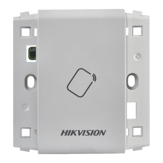
Page 8: Rear View
2.2 Rear View Figure 2-2 Rear View of DS-K1106 Series Name PSAM Card Slot (available for CPU card reader) DIP Switch Cable Interface of RS-485, Power, LED Control, etc. Serial Port Chapter 3 Installation 3.1 Installing PSAM Card PSAM card slot is only available for CPU card reader. -
Page 9: Introduction For Dip Switch
Figure 3-1 PSAM Card Slot 3.2 Introduction for DIP Switch The DIP switch module is shown below. The No. of DIP switch from left to right is 1 ~ 8. Figure 3-2 DIP Switch Module Table 3-1 Description of DIP Switch Icon Description Represent 1 in binary mode... -
Page 10: Definition Of Cable
Description DIP Switch Status 0: 0 Read card No. or file in card. 1: read card No; (Only available for CPU card 0: read file in card. reader.) Wiegand protocol or RS-485 1: Wiegand protocol; protocol. 0: RS-485 protocol. 1: Wiegand protocol Wiegand Protocol of 26-bit;... -
Page 11: Wiring Cables
3.4 Wiring Cables Purpose: Wire the cables between controller and card reader, thus to establish the communication between them. Steps for RS-485 communication mode: Set the DIP switch of No. 6 as 0. Set the DIP switch of No. 1 ~ 5 for RS-485 address and reading card mode. - Page 12 Controller Card Reader Figure 3-4 Wiring for RS-485 Communication Mode Steps for Wiegand communication mode: Set the DIP switch of No. 6 as 1. Set the DIP switch of No. 5 and 7 for reading card mode and Wiegand protocol. For details, please refer to 3.2 Introduction for DIP Switch.
-
Page 13: Installing Card Reader
Controller Card Reader Figure 3-5 Wiring for Wiegand Communication Mode 3.5 Installing Card Reader Before you start: Set the DIP switch. For details, refer to 3.2 Introduction for DIP Switch. -
Page 14: Chapter 4 Sound Prompt And Indicator
Installation for DS-K1101/ 02/ 03/ 04 series card reader Steps: Fix the gang box on the wall or other place. Connect the cables between controller and card reader. For details, refer to 3.4 Wiring Cables. Push the card reader to match the fixed gang box. - Page 15 starting up process is completed. During using the card reader, it will send out different sounds prompt and the LED indicator on it have different statuses. You can refer to tables below for detailed information. Table 4-1 Description of Prompt Sound Sound Prompt Description RS-485 protocol: Pressing keys prompt;...
- Page 16 LED Indicator Status Description Red and Keeping Available for reading file mode of CPU rapidly blinking card: PSAM is not inserted or undetected.