Table of Contents
Advertisement
Quick Links
Advertisement
Table of Contents

Related Manuals for HIKVISION DS-K1106M


Summary of Contents for HIKVISION DS-K1106M
- Page 1 DS-K1106 Series Card Reader User Manual UD.6L0206D1175A01...
- Page 2 ALL RIGHTS RESERVED. Any and all information, including, among others, wordings, pictures, graphs are the properties of Hangzhou Hikvision Digital Technology Co., Ltd. or its subsidiaries (hereinafter referred to be “Hikvision”). This user manual (hereinafter referred to be “the Manual”) cannot be reproduced, changed, translated, or distributed, partially or wholly, by any means, without the prior written permission of Hikvision.
- Page 3 DAMAGES, INCLUDING, AMONG OTHERS, DAMAGES FOR LOSS OF BUSINESS PROFITS, BUSINESS INTERRUPTION, OR LOSS OF DATA OR DOCUMENTATION, IN CONNECTION WITH THE USE OF THIS PRODUCT, EVEN IF HIKVISION HAS BEEN ADVISED OF THE POSSIBILITY OF SUCH DAMAGES. REGARDING TO THE PRODUCT WITH INTERNET ACCESS, THE USE OF PRODUCT SHALL BE WHOLLY AT YOUR OWN RISKS.
-
Page 4: Table Of Contents
Content CHAPTER 1 PREVENTIVE AND CAUTIONARY TIPS ....2 CHAPTER 2 INTRODUCTION ..........3 ............3 RONT .............. 4 CHAPTER 3 INSTALLATION ..........4 PSAM C ..........4 NSTALLING DIP S ......... 5 NTRODUCTION FOR WITCH ..........6 EFINITION OF ABLE ............ -
Page 5: Chapter 1 Preventive And Cautionary Tips
Chapter 1 Preventive and Cautionary Tips To guarantee the card reader works properly, please read and obey the notes below. If the card reader is powered by the controller, the power supply distance is recommended to be no longer than 100m. If the distance is longer than 100m, you are advised to power the card reader by external 12V (range: -%10 ~ +%10) DC power supply, which is nonswitched and linear. -
Page 6: Chapter 2 Introduction
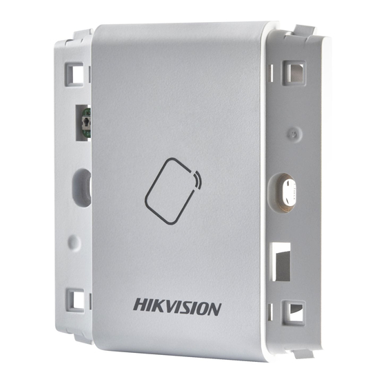
RS-485 protocol or Wiegand protocol. And a build-in tamper-proof module helps to protect card reader from malicious damage. As to the physical appearance, the PC+ABS material makes water proof and dust proof possible in poor environment. 2.1 Front View Figure 2-1 DS-K1106M/DS-K1106C/DS-K1106S... -
Page 7: Rear View
2.2 Rear View Figure 2-2 Rear View of DS-K1106 Series Name PSAM Card Slot (available for CPU card reader) DIP Switch Cable Interface of RS-485, Power, LED Control, etc. Serial Port Chapter 3 Installation 3.1 Installing PSAM Card PSAM card slot is only available for CPU card reader. Insert the PSAM card into the slot according to the direction shown below. -
Page 8: Introduction For Dip Switch
Figure 3-1 PSAM Card Slot 3.2 Introduction for DIP Switch The DIP switch module is shown below. The No. of DIP switch from left to right is 1 ~ 8. Figure 3-2 DIP Switch Module Table 3-1 Description of DIP Switch Icon Description Represent 1 in binary mode... -
Page 9: Definition Of Cable
Description DIP Switch Status 1: 1 1 ~ 4 Address of RS-485 0: 0 Read card No. or file in card. 1: read card No; (Only available for CPU card 0: read file in card. reader.) Wiegand protocol or RS-485 1: Wiegand protocol;... -
Page 10: Wiring Cables
Color Description PWR (DC +12V) 3.4 Wiring Cables Purpose: Wire the cables between controller and card reader, thus to establish the communication between them. Steps for RS-485 communication mode: Set the DIP switch of No. 6 as 0. Set the DIP switch of No. 1 ~ 5 for RS-485 address and reading card mode. - Page 11 Controller Card Reader Card Reader Figure 3-4 Wiring for RS-485 Communication Mode Steps for Wiegand communication mode: Set the DIP switch of No. 6 as 1. Set the DIP switch of No. 5 and 7 for reading card mode and Wiegand protocol.
-
Page 12: Installing Card Reader
Controller Card Reader Card Reader Figure 3-5 Wiring for Wiegand Communication Mode 3.5 Installing Card Reader Before you start: Set the DIP switch. For details, refer to 3.2 Introduction for DIP Switch. -
Page 13: Chapter 4 Sound Prompt And Indicator
Steps: Fix the gang box on the wall or other place. Connect the cables between controller and card reader. For details, refer to 3.4 Wiring Cables. Push the card reader to match the fixed gang box. Fasten the screw to keep the components together. - Page 14 During using the card reader, it will send out different sounds prompt and the LED indicator on it have different statuses. You can refer to tables below for detailed information. Table 4-1 Description of Prompt Sound Sound Prompt Description RS-485 protocol: Pressing keys prompt; Swiping card prompt;...
Need help?
Do you have a question about the DS-K1106M and is the answer not in the manual?
Questions and answers