
Related Manuals for Bristan BL3105


Summary of Contents for Bristan BL3105
- Page 1 Installation Instructions and User Guide Bliss Electric Showers Please keep this booklet for future reference. Installer, when you have read these instructions please ensure you leave them with the user.
-
Page 2: Table Of Contents
Welcome to your new Bristan electric shower. Featuring a contemporary design with lots of fun features, Bristan’s electric shower collection has been designed to be enjoyable to fit and to use. It has also been designed and tested in the UK to all of the relevant British Standards. -
Page 3: Important Safety Information
Troubleshooting section (see page 21) or contact Bristan Customer Services. • All products manufactured and supplied by Bristan are safe provided • Do not crush or kink the shower they are installed, used correctly hose, this could damage the hose,... -
Page 4: General Information
General Safety Information • Always switch off the power at the consumer unit and isolate the electrical supply before making any electrical connections or if you have to remove the cover of an installed unit. • The unit must be mounted on the finished wall surface (usually tiled). -
Page 5: Product Features
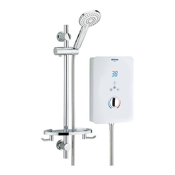
Product Features 1. Temperature Indication Water temperature indication Digital Display. The Digital Display will only light up once the STOP/START touch button is pressed, then the temperature display will start to count up, depending on the position of control 6. Note: The Digital Display is an indication of the water temperature inside the unit, not the outlet water temperature. -
Page 6: Specifications
Right hand side: Bottom, Rear (bottom) Recommended Usage Domestic Heavy Commercial Light Commercial Health Care Product Fiche Model BL385 W BL395 W BL3105 W BL385 B BL395 B BL3105 B Declared Load Profile Water Heating Energy Efficiency Class Water Heating Energy Efficiency 38.5 38.6 38.6... -
Page 7: Electrical Requirements
Electrical Requirements Warning: This appliance MUST Isolating Double pole valve switch be earthed! Rating at 240V Rating at 230V 8.5kW 7.8kW For Cable Capacity 9.5kW 8.7kW see Cable Current Shower unit Carrying Capacity 10.5kW 9.5kW Table on page 8 The Electrical Installation and Circuit Protection of this shower must comply with current I.E.E Wiring Regulations (BS 7671) and Building Regulations (Part P). - Page 8 Electrical Requirements cont. It is a requirement that a residual current device (RCD) formerly known as an earth leakage circuit breaker (ELCB) with a tripping current of 30mA, is incorporated in the circuit. This may be part of the existing consumer unit or a separate unit. For close circuit protection DO NOT use a rewireable fuse.
-
Page 9: Water Requirements
Water Requirements This fitting needs to be installed in accordance with the following Installation Requirements and Notes (IRN) to ensure they meet the requirements of the Water Supply (Water Fittings) Regulations 1999 and the Scottish Byelaws 2004. The fitting shall be installed so that its outlet discharges above the spill-over level of any fixed appliance as indicted on the illustration below. -
Page 10: Fixing Your Shower To The Wall
Fixing Your Shower to the Wall Remove Warning: Please check for any hidden pipes and cables before cover screws drilling holes in the wall. Remove the 4 cover retaining screws and lift off the cover. Do not try to remove the control knob from the cover. It is an integral part of the cover and must not be removed. -
Page 11: Plumbing Connections
Plumbing Connections Inlet Entry Options Select the inlet option most suited to your situation. Bottom left inlet entry Bottom right inlet entry Top left inlet entry Rear left inlet entry - Rear right inlet entry - Rear left inlet entry - requiring rear access requiring rear access using a 15mm compression elbow... - Page 12 Plumbing Connections cont. Warning: The outlet of the shower acts as a vent and must not be blocked, restricted or connected to any tap/closure device other than the handset supplied. Do not solder within 300mm of the shower unit or allow solder or flux to fall onto the casings.
- Page 13 Plumbing Connections cont. Hole Cover Fitting Back of unit Top left entry: Depending on your choice of cold-water entry direction, you may need to remove thin areas of plastic cover to facilitate pipe work entry down through the top left of the unit. Bottom entry: Depending on your choice of cold-water entry direction, fit ‘hole covers’...
-
Page 14: Electrical Connections
Electrical Connections Warning: This appliance and all connecting metal pipe work must be earthed. • Ensure that an earth continuity conductor is securely and permanently connected to all exposed metal parts of other services and appliances within the room where the shower is installed. - Page 15 Electrical Connections cont. Electrical Connection Entry Point Options - continued Alternatively, if preferred, it is possible to route the cable from the rear bottom right or bottom right positions as shown below by stripping the sheath back further. Select the cable inlet option most suited to your situation. ...
- Page 16 Electrical Connections cont. Switch OFF the electricity supply at the consumer unit. The power cable entry point is shown on the diagram. Electrical connection to be made at the terminal block as follows: Earth cable to the terminal marked with the Earth symbol Neutral cable to the terminal marked N Live cable to the terminal marked L Important: Terminals must be fully tightened onto the cables...
-
Page 17: Fitting Your Riser Rail To The Wall
Fixing Your Riser Rail to the Wall Fitting the Riser Rail Before proceeding with fitting the rail, identify each of the items supplied using the illustration on the right. The Slider should not be removed from the rail during fitting. The underside of the slider has a button to release the slider and allows Large hole the height to be adjusted. -
Page 18: Commissioning - Testing The System
Commissioning - Testing the System Warning: Before using the shower for the first time, it should receive a final flush through and filter clean to remove any remaining debris that may be in the pipe work or hose and to ensure the heater unit contains water before the electrical elements are switched on. -
Page 19: Operating The Shower
Operating the Shower Please ensure the commissioning procedure has been carried out. If you did not fit this shower yourself and you are about to use it for the first time, check with the installer to ensure he or she has run the commissioning procedure as described on page 18. -
Page 20: Maintenance
Clean the Inlet Filter and Clean the Outlet Hose Mesh Filter. Cleaning the Showerhead Your Bristan showerhead has a rub-clean pad for easy cleaning. Simply rub your fingers across the rubber spray jets regularly and before you turn the shower on to remove any scale or debris. -
Page 21: Troubleshooting
Maintenance cont. Cleaning the Inlet Filter Periodically remove the inlet filter and rinse under clean running water. First isolate the electrical and water supply to the unit. To remove: Turn anti-clockwise using a large flatblade screwdriver. Note: A small amount of water will be discharged when the filter is removed - this is normal. -
Page 22: Guarantee
The registration of your 24 hours in advance of the agreed date and time. personal details is purely for Bristan use and the remaining information helps us to make products for the future. Should a product be discontinued, spare parts stocks... -
Page 23: Spare Parts
Spare Parts Please visit: www.bristan.com/sparesfinder in order to find spare parts for this product. Part No. Description Parts List Quantity 131-140-S-85 Stabiliser Valve Ass. 8.5 kW Stabiliser Valve x1, inc. O-rings x2 131-140-S-95 Stabiliser Valve Ass. 9.5 kW Stabiliser Valve x1, inc. O-rings x2 131-140-S-105 Stabiliser Valve Ass. - Page 24 Spare Parts Need help? Give us a call on 0844 701 6273 and speak to one of our trained advisors.
- Page 25 Spare Parts cont. 01/03 01/03 Part No. Description Parts List Quantity 1408A0A Riser Rail End Cap Riser Rail End Cap x1 11043A0A Wall Bracket Ass. Wall Brackets x2, Wall Bracket End Caps x2, Screws x2, Wall Plugs x2 207041-012C Riser Rail Ass. Riser Rail x1, Riser Rail End Caps x2 1625A0A Slider/Handset Holder...
-
Page 26: Notes
Notes Please use this space to add any notes you or your installer may have regarding the plumbing system / installation of this product. Need help? Give us a call on 0844 701 6273 and speak to one of our trained advisors. - Page 27 Notes Please use this space to add any notes you or your installer may have regarding the plumbing system / installation of this product. Need help? Give us a call on 0844 701 6273 and speak to one of our trained advisors.
- Page 28 Issue FI ES Bliss - I Part Number 131 - 724 Bristan Group Ltd. Birch Coppice Business Park Dordon Tamworth Staffordshire B78 1SG Web: www.bristan.com Email: enquire@bristan.com A Masco Company...
Need help?
Do you have a question about the BL3105 and is the answer not in the manual?
Questions and answers