Table of Contents
Advertisement
Quick Links
It is of vital importance, before attempting
to operate your engine,
general 'SAFETY INSTRUCTIONS AND
WARNINGS' section on pages 2-4 of this
booklet and to strictly adhere to the advice
contained therein.
Also, please study the entire contents of this
instruction manual, so as to familiarize
yourself with the controls and other features
of the engine.
Keep these instructions in a safe place so
that you may readily refer to them whenever
necessary.
It is suggested that any instructions supplied
with the aircraft, radio control equipment,
etc., are accessible for checking at the same
time.
CONTENTS
INTRODUCTION, TOOLS AND ACCESSORIES
to read the
2-4
5
6-7
8-9
10-11
12
13-14
14-18
18-19
19-21
1
Horizontally-opposed four-cylinder
overhead-valve four-stroke-cycle
ENGINE EXPLODED VIEW
ENGINE PARTS LIST
CARBURETOR EXPLODED VIEW &
ENGINE THREE VIEW DRAWINGS
22
22
23-25
26
27
28
29
30
Advertisement
Table of Contents

Related Manuals for O.S. engine PEGASUS 320


Summary of Contents for O.S. engine PEGASUS 320
-
Page 1: Table Of Contents
Horizontally-opposed four-cylinder etc., are accessible for checking at the same overhead-valve four-stroke-cycle time. CONTENTS SAFETY INSTRUCTIONS AND WARNINGS ABOUT YOUR O.S. ENGINE FLIGHT INTRODUCTION, TOOLS AND ACCESSORIES CARE AND MAINTENANCE 23-25 ENGINE PARTS NAME VALVE CLEARANCE ADJUSTMENT... -
Page 2: Safety Instructions And Warnings About Your O.s. Engine
600 feet(180 metres) per second, it will be understood all times. that such a failure could result in serious injury, (see 'NOTES' If at some future date, your O.S. engine is acquired by section relating to propeller safety). another person, we would respectfully request that these instructions are also passed on to its new owner. - Page 3 NOTES Use an electric starter for this engine. The wearing of safety glasses is also strongly recommended. Take care that the glow plug clip or battery leads do not come into contact with the propeller. Also check the linkage to the throttle arm. A disconnected linkage could also foul the propeller. After starting the engine, carry out any needle-valve readjustments from a safe position behind the rotating propeller.
-
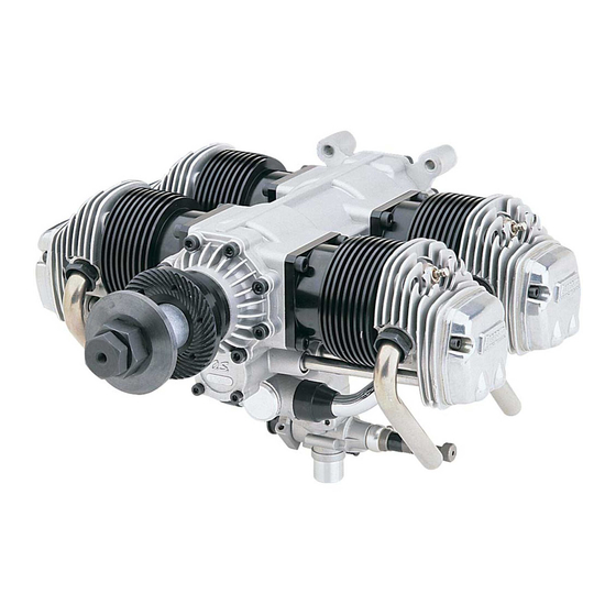
Page 4: Engine Parts Name
ENGINE PARTS NAME Photo. 2 Crankcase No.1 Cylinder No.3 Cylinder No.2 Cylinder Lock Nut Propeller Nut No.4 Cylinder Propeller Washer Front Housing Choke Valve Photo. 3 Fuel Inlet Carburetor Intake Manifold Breather Nipple Exhaust Pipe Rocker Cover Drain Nipple Rear Housing Cylinder Head... -
Page 5: Installation
INSTALLATION The FF-320 is equipped with a strong cast aluminum radial- Needle-valve extension type mount to enable it to be bolted securely to the firewall The needle-valve with this engine is designed to incorporate (front bulkhead) of the aircraft. an extension so that, when the engine is enclosed within the It is essential that the firewall is strong and rigid (e.g. -
Page 6: Propeller
PROPELLER The choice of propeller depends on the design and weight of PROPELLER & SPINNER ATTACHMENT the aircraft and on the type of flying in which you will be There is a risk, particularly with powerful four-stroke engines, engaged. Determine the best size and type after practical of the propeller flying off if the prop nut loosens due to experimentation. -
Page 7: Glowplugs
GLOWPLUGS The FF-320 is supplied with an O.S. Type F glowplug, When to replace the glowplug specially designed for O.S. four-stroke engines. Apart from when actually burned out, a plug may need to be replaced because it no longer delivers its best performance, The role of the glowplug such as when: With a glowplug engine, ignition is initiated by the application... -
Page 8: Fuel And Lubrication, Starting
Glowplug leads Glowplug re-heat The plug leads are fitted with special snap-on connectors Under normal conditions, the FF-320 will idle sufficiently that ensure firm contact with O.S. plug. They are a "click" fit slowly with the throttle closed to permit a safe landing and are not suitable for use with most other makes of approach. - Page 9 Excess fuel in the carburetor may drip into the engine Open the throttle valve fully, close the choke valve and turn compartment when the choke valve is reopened. Therefore, the propeller counter-clockwise through three revolutions. (Fig.19 & 20) it is advisable to drill a drain hole in the bottom of the engine bay or cowling and to apply fuelproof paint to the Fig.19 Fig.20...
-
Page 10: Running-In ("Breaking-In")
Adjust the needle-valve RUNNING-IN ("Breaking-in") Abrupt adjustment of the needle-valve may cause the Obtain an 18x12 or 20x8 propeller for running-in. engine to stop, especially when it is new and insufficiently run-in. 1. Running-in on the ground As the speed of the engine does not instantly change with needle-valve readjustment, small movements, with pauses Start the engine between, are necessary to arrive at the optimum setting. - Page 11 Start the engine. Disconnect the glowplugs from the battery. open the throttle fully . Approx 40˚ open from maximum r.p.m. setting. Adjust the needle-valve. Make sure that all 4 cylinders are firing. Close the throttle gradually. The position where the lowest Set the idle speed.
-
Page 12: Flight
Adjusting the mixture control valve of the + mark about 1/12 turn (30 ). Normal safe idle speeds are in the region of 2,000 r.p.m.. If the engine hesitates, puffing out Mixture Control Screw a good deal of smoke, before NOTE: picking up to full speed, it is As this is four-cylinder four-stroke-cycle engine, firing... -
Page 13: Valve Clearance Adjustment
VALVE CLEARANCE ADJUSTMENT ALL O.S. four-stroke engines have their valve (tappet) Remove all the glowplugs except the one installed in the clearances correctly set before they leave the factory. cylinder that you want to check. However, if, after many hours of running time have been Note: logged, a loss of power is detected, or if the engine has to Each glowplug should be re-installed in to the original... - Page 14 Re-tighten locknut while holding adjusting screw stationary. (Fig.38.) Hold at the screw head. Tighten Locknut. Fig.38 Remove 0.04mm feeler, rotate prop through two revolutions and recheck gap. If clearance is correct, loosen the locknut on the other rocker-arm and repeat steps 1 to 5 above. Finally, replace rocker box cover.
-
Page 15: Parts List
EXPLODED VIEW 26-1 C.M3.5x12 C.M3x16 C.M4x22 C.M3.5x10 31 32 12-3 C.M3.5x12 12-2 16-2 16-1 16-3 12-1 13-3 C.M2.6x8 13-2 C.M3.5x15 13-1 11-2 11-1 C.M3x15 11-2 N.+M3x22 C.M3.5x20 C.M3x8 11-3 C.M2.6x7 Type of screw C...Cap Screw M...Oval Fillister-Head Screw F...Flat Head Screw N...Round Head Screw S...Set Screw PARTS LIST Description Description... -
Page 16: O.s. Genuine Parts & Accessories
CARBURETOR EXPLODED VIEWS & PARTS LIST Code No. Description S.M3x3 26381501 Set-screw 24981405 Throttle Lever Assembly 26381501 Set-screw 46481320 Mixture Control Screw Assembly 22781800 "O" Ring (2pcs.) S.M3x3 46481330 Mixture Control Screw Holder Assembly 26381501 Set-screw S.M3x3 46481200 Carburetor Rotor 46281340 Mixture Control Valve Pin 46481310... - Page 17 THREE VIEW DRAWING Specifications Displacement 13,26cc x 4 / 0.809cu.in. x 4 Bore 27,7mm / 1.091in. Stroke 22,0mm / 0.866in. PracticalR.P.M. 1,800-8,500r.p.m. Output Weight 2,190g / 77.3oz. 4- 5.2 181.5 Dimensions(mm) 6-15 3-Chome Imagawa Higashisumiyoshi-ku Osaka 546-0003, Japan TEL. (06) 6702-0225 FAX.
Need help?
Do you have a question about the PEGASUS 320 and is the answer not in the manual?
Questions and answers