Table of Contents
Advertisement
It is of vital importance, before attempting to
operate your engine,
'SAFETY INSTRUCTIONS AND WARNINGS'
section on pages 2-4 of this booklet and to
strictly adhere to the advice contained therein.
•
Also, please study the entire contents of this
instruction manual, so as to familiarize
yourself with the controls and other features of
the engine.
•
Keep these instructions in a safe place so that
you may readily refer to them whenever
necessary.
•
It is suggested that any instructions supplied
with the aircraft, radio control equipment, etc.,
are accessible for checking at the same time.
CONTENTS
INTRODUCTION, BEFORE INSTALLING THE ENGINE
GLOWPLUGS, FUEL
PROPELLER, MIXTURE CONTROLS
RUNNING-IN ("Breaking-in")
MIXTURE CONTROL ADJUSTMENT CHART
to read the general
2-4
5
6
7
7-8
9
9-10
10-11
12
MIXTURE CONTROL VALVE ADJUSTMENT,
REALIGNMENT OF MIXTURE CONTROL VALVE,
SUBSEQUENT STARTING PROCEDURE
VALVE ADJUSTING
ENGINE EXPLODED VIEW
ENGINE PARTS LISTS
PARTS LIST, THREE VIEW DRAWING
−1−
13
14
15
16
17
18
Advertisement
Table of Contents

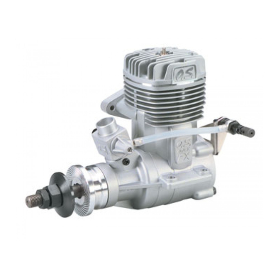
Summary of Contents for O.S. engine O.S. Max-160FXRing
-
Page 1: Table Of Contents
CONTENTS SAFETY INSTRUCTIONS AND MIXTURE CONTROL VALVE ADJUSTMENT, WARNINGS ABOUT YOUR O.S. ENGINE REALIGNMENT OF MIXTURE CONTROL VALVE, SUBSEQUENT STARTING PROCEDURE INTRODUCTION, BEFORE INSTALLING THE ENGINE BASIC ENGINE PARTS SUBSEQUENT READJUSTMENT, CARBURETOR CLEANLINESS. -
Page 2: Safety Instructions And Warnings About Your O.s. Engine
600 feet(180 meters) per second, it will be understood all times. that such a failure could result in serious injury, (see 'NOTES' If at some future date, your O.S. engine is acquired by section relating to propeller safety). another person, we would respectfully request that these instructions are also passed on to its new owner. -
Page 3: Basic Engine Parts
NOTES • Take care that the glow plug clip or battery leads do not come into contact with the propeller. Also check the linkage to the throttle arm. A disconnected linkage could also foul the propeller. • After starting the engine, carry out any needle-valve readjustments from a safe position behind the rotating propeller. -
Page 4: Installation Of The Engine
How to fasten the mounting screws. INSTALLATION OF THE ENGINE Tighten second nut firmly 5mm steel Allen 5mm steel nut down onto first nut. screw NOTE: Be sure to secure large enough air intake and Tighten this nut first. Spring washer Spring washer outlet area for cooling the engine in order not to overheat or lock washer... - Page 5 The role of the glowplug FUEL With a glowplug engine, ignition is initiated by the application of a 1.5-volt power source. When the battery is disconnected, Select, by practical tests, the most suitable fuel from among the heat retained within the combustion chamber remains the best quality fuels available in your country for model use.
-
Page 6: Starting
−10− ◆ During subsequent flights, the needle-valve can be Needle-valve adjustment diagram gradually closed to give more power. However, if the engine shows signs of running too lean, the Practical best(optimum) needle-valve setting ⑥ next flight should be set richer. After a total of ten to fifteen Clear, high-pitched two-stroke ⑦... - Page 7 −12− −13−...
-
Page 8: Subsequent Readjustment
SUBSEQUENT READJUSTMENT ENGINE CARE AND MAINTENANCE Once the engine has been run-in and the controls properly At the end of each operating session, drain out any fuel that set up, it should be unnecessary to alter the mixture settings; may remain in the fuel tank. except to make minor adjustments to the Needle-Valve Next, energize the glowplug and try to restart the engine to occasionally, to take account of variations in climatic... - Page 9 −16− −17−...
-
Page 10: Carburetor Exploded Views
CARBURETOR EXPLODED VIEW & THREE VIEW DRAWING Dimensions(mm) PARTS LIST SPECIFICATIONS N.+M3×6 ■ Displacement 26.23 cc (1.60 cu.in.) ■ Bore 33.6 mm (1.323 in.) ■ Stroke 29.6 mm (1.165 in.) ■ Practical R.P.M. 1,800-10,000 r.p.m. ⑤ ④ ■ Power output 3.7 ps / 3.75 hp / 9,000r.p.m.


Need help?
Do you have a question about the O.S. Max-160FXRing and is the answer not in the manual?
Questions and answers