Table of Contents
Advertisement
It is of vital importance, before attempting to
operate your engine,
'SAFETY INSTRUCTIONS AND WARNINGS'
section on pages 2-4 of this booklet and to
strictly adhere to the advice contained therein.
Also, please study the entire contents of this
instruction manual, so as to familiarize
yourself with the controls and other features of
the engine.
Keep these instructions in a safe place so that
you may readily refer to them whenever
necessary.
It is suggested that any instructions supplied
with the aircraft, radio control equipment, etc.,
are accessible for checking at the same time.
CONTENTS
INTRODUCTION, INSTALLING THE GLOWPLUG
to read the general
2-4
5
6
7
8
9-10
10
11
12
ENGINE EXPLODED VIEWS &
ENGINE PARTS LISTS
CARBURETTOR EXPLODED VIEWS &
ENGINE THREE VIEW DRAWINGS
NOTE
1
12-13
14-15
15
16-17
18
19
20-21
22
23
24
Advertisement
Table of Contents

Related Manuals for O.S. engine FS-120S-E


Summary of Contents for O.S. engine FS-120S-E
-
Page 1: Table Of Contents
CONTENTS SAFETY INSTRUCTIONS AND STARTING 12-13 WARNINGS ABOUT YOUR O.S. ENGINE RUNNING-IN 14-15 INTRODUCTION, INSTALLING THE GLOWPLUG BASIC ENGINE PARTS IDLE MIXTURE ADJUSTMENT RELOCATION OF CARBURETTOR CONTROLS... -
Page 2: Safety Instructions And Warnings About Your O.s. Engine
600 feet(180 metres) per second, it will be understood all times. that such a failure could result in serious injury, (see 'NOTES' If at some future date, your O.S. engine is acquired by section relating to propeller safety). another person, we would respectfully request that these instructions are also passed on to its new owner. -
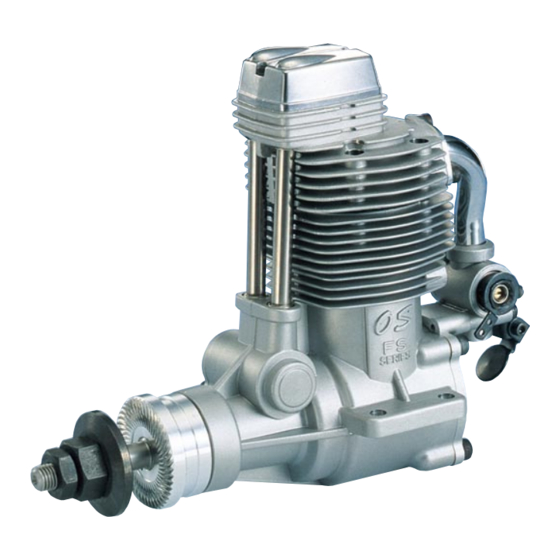
Page 3: Basic Engine Parts
WITHOUT the glowplug battery being reconnected. Remember this if you wish to avoid the risk of a painfully rapped knuckle! INTRODUCTION BASIC ENGINE PARTS The O.S. FS-120S-E is an aircooled, overhead-valve four- stroke-cycle engine for model aircraft use. It is produced by the world' s pldest and largest model engine manufac- Rocker Cover turing company: a company which also pioneered the quantity production at model four-stroke-cycle engines. -
Page 4: Relocation Of Carburettor Controls
The FS-120S-E is equipped with a spring-loaded choke valve. interchangeable by reversing the carburetor. This can be The choke valve operating lever can be located right or left by done as follows: transposing the hexagon nut and cap screw. -
Page 5: Exhaust Header Pipe And Silencer
THROTTLE LINKAGE EXHAUST HEADER PIPE & SILENCER Before connecting the throttle to its servo, make sure that the Install these in the following sequence. throttle arm and linkage safely clear any adjacent part of the Screw the header pipe into the cylinder head until it " bottoms airframe structure, etc., as the throttle is opened and closed. -
Page 6: Fuel
Since the FS-120S-E is intended to be started with an electric FUEL starter, the addition of a spinner assembly for centering the starter sleeve is desirable. Special propeller locknut sets are The FS-120S-E should be operated on a methanol based fuel available for use with spinners. -
Page 7: Carburetor
CARBURETTOR Throttle Stop Screw Three adjustable controls are provided on this carburetor. • The Needle Valve This is used to establish the fuel/air mixture strength required for full power when the throttle is fully open. • The Mixture Control Valve (Mixture Control Screw) This is used to establish the mixture strength required for steady idling and a smooth transition to medium speeds. -
Page 8: Running-In
WARNING: RUNNING-IN ("Breaking-in") When ground running the engine, avoid dusty or sandy For long life and peak performance, every engine needs locations. If dust or grit is drawn into the engine, this can special treatment when new, known as "running-in" or have a ruinous effect, drastically shortening engine life in "breaking-in". -
Page 9: Valve Adjusting
0.04mm and 0.10mm(0.0015-0.004 inch), measured between valve stem and rocker arm. Use Valve clearances are correctly set before any O.S. engine the 0.04mm and 0.10mm feeler gauges to check leaves the factory and, in normal use, will seldom require clearances. -
Page 10: Care And Maintenance
CARE AND MAINTENANCE To ensure that you obtain long life and peak performance from your Clean the exterior of the engine with a clean cotton cloth.If engine, observe the following. this is not done, oil and dirt will burn onto the outside of the engine each time it is run and the engine will soon become Avoid running the engine under dusty conditions. -
Page 11: Parts List
PARTS LIST Code No. Description Code No. Description 45513010 Screw Set 45502040 Crankshaft 45504210 Rocker Cover 45530010 Crankshaft Ball Bearing(Rear) 45561401 Rocker Support Assembly Gasket Set 45514010 45561410 Rocker Support 45501020 Crankcase Rocker Arm Retainer(2pcs.) 45761600 22681953 Breather Nipple Rocker Arm Assembly(1pair) 45561010 45231100 Camshaft Ball Bearing (1pcs.) -
Page 12: Three View Drawing
CARBURETOR EXPLODED VIEWS & PARTS LIST Type of screw S.3X3 C...Cap Screw M...Oval Fillister-Head Screw F...Flat Head Screw N...Round Head Screw S...Set Screw S.3X3 N.+M3X22 Description Code No. 24981405 Throttle Lever Assembly 26381501 Set Screw 45581200 Carburetor Rotor 26781309 Mixture Control Valve Assembly 24881824 "O"... - Page 13 MEMO 6-15 3-Chome Imagawa Higashisumiyoshi-ku Osaka 546-0003, Japan TEL. (06) 6702-0225 FAX. (06) 6704-2722 URL : http://www.os-engines.co.jp Copyright 2003 by O.S.Engines Mfg. Co., Ltd. All rights reserved. Printed in Japan. 60090510 061103...
Need help?
Do you have a question about the FS-120S-E and is the answer not in the manual?
Questions and answers