Table of Contents
Advertisement
It is of vital importance, before attempting to
operate your engine, to read the general
'SAFETY INSTRUCTIONS AND WARNINGS'
section on pages 2-6 of this booklet and to strictly
adhere to the advice contained therein.
Also, please study the entire contents of this
instruction manual, so as to familiarize yourself
with the controls and other features of the
engine.
Keep these instructions in a safe place so that
you may readily refer to them whenever
necessary.
It is suggested that any instructions supplied
with the aircraft, radio control equipment, etc.,
are accessible for checking at the same time.
Advertisement
Table of Contents

Subscribe to Our Youtube Channel
Related Manuals for O.S. engine MAX-25LA


Summary of Contents for O.S. engine MAX-25LA
- Page 1 It is of vital importance, before attempting to operate your engine, to read the general 'SAFETY INSTRUCTIONS AND WARNINGS' section on pages 2-6 of this booklet and to strictly adhere to the advice contained therein. Also, please study the entire contents of this instruction manual, so as to familiarize yourself with the controls and other features of the engine.
-
Page 2: Table Of Contents
CONTENTS TROUBLE SHOOTING WHEN THE SAFETY INSTRUCTIONS AND WARNINGS ENGINE FAILS TO START ABOUT YOUR O.S. ENGINE CARE AND MAINTENANCE INTRODUCTION OPTIONAL PARTS & ACCESSORIES INSTALLATION OF THE ENGINE 10LA ENGINE EXPLODED VIEW & INSTALLATION OF SILENCER PARTS LIST BEFORE STARTING 15/25LA ENGINE EXPLODED VIEW &... -
Page 3: Safety Instructions And Warnings About Your O.s. Engine
SAFETY INSTRUCTIONS AND WARNINGS ABOUT YOUR O.S. ENGINE Remember that your engine is not a "toy", but a highly efficient internal- combustion machine whose power is capable of harming you, or others, if it is misused. As owner, you, alone, are responsible for the safe operation of your engine, so act with discretion and care at all times. - Page 4 WARNINGS • Never touch, or allow any object to come • Model engine fuel is also highly flammable. Keep it away from open flame, into contact with, the rotating excessive heat, sources of sparks, or propeller and do not crouch anything else which might ignite over the engine when it is it.
- Page 5 NOTES • • This engine was designed for model If you remove the glowplug from the engine aircraft. Do not attempt to use it for any and check its condition by connecting the other purpose. battery leads to it, do not hold the plug with bare fingers.Use an appropriate tool or a •...
- Page 6 NOTES • • Always check the tightness of the propeller Discard any propeller which has become nut and retighten it, if necessary, before split, cracked, nicked or otherwise rendered restarting the engine, particularly in the unsafe. Never attempt to repair such a case of four-stroke-cycle engines.
- Page 7 NOTES • • Adjust the throttle linkage so that the engine For their safety, keep all onlookers stops when the throttle stick and trim lever (especially small children) well back (at on the transmitter are fully retarded. least 20 feet or 6 meters) when preparing Alternatively, the engine may be stopped by your model for flight.
-
Page 8: Introduction
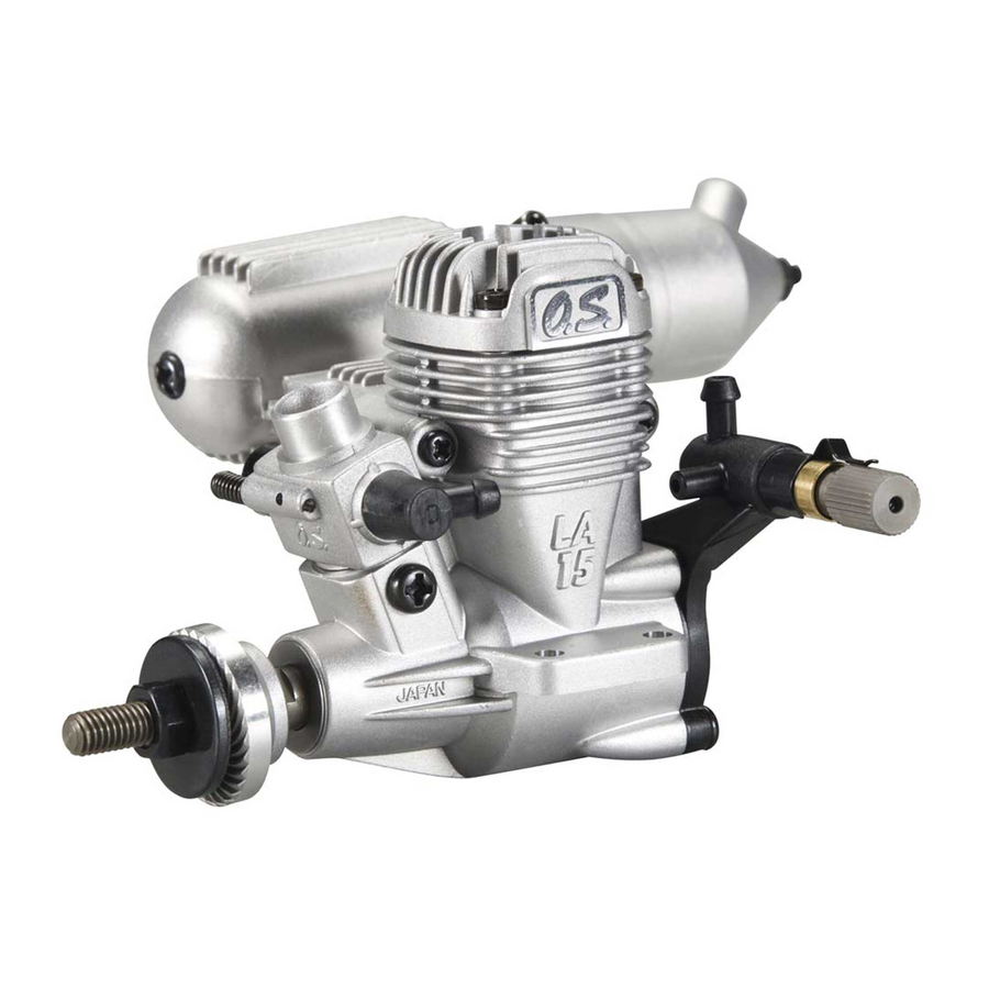
Glowplug Cylinder head INTRODUCTION THE MAX-10LA,15LA,25LA have been developed to meet the requirements of beginners and sport flyers. Carburettor Fuel outlet Of modern design and having a separate needle- Needle valve valve unit mounted at the rear, where manual adjustment is safely remote from the rotating propeller, they offer the advantages of reliability and easy handling, at lower cost. -
Page 9: Installation Of The Engine
How to fasten the mounting screws. INSTALLATION Installation in the model Tighten second nut firmly down onto first nut. O.S. radial motor mount A typical method of beam (Available as an optional extra part. 3mm steel nuts mounting is shown below,left. Tighten this nut first. -
Page 10: Installation Of Silencer
NEEDLE-VALVE EXTENSION Assembly screw Cone baffle The needle-valve supplied with these engines is Turn to requlred position designed to incorporate an extension so that, when the engine is enclosed within the fuselage, the needle-valve may be adjusted from the outside. Exhaust outlet Cut a commercially available rod to the required length, bend one end to an L shape, insert it into... -
Page 11: Before Starting 10
Warning (Very hot) BEFORE STARTING Never touch the nichrome wire while the battery is Tools, accessories, etc. connected. The following items are necessary for operating the engine. Resistance coil (nichrome wire) 1 Fuel Model glowplug engine fuel of good quality, preferably containing a small percentage of nitromethane. - Page 12 6 Battery leads 9 Fuel can filter These are used to conduct Fit a filter to the outlet tube of current from the battery to the your refuelling container to Fuel Can Filter glowplug. Basically, two leads, prevent entry of foreign with clips, are required, but, for matter into the fuel tank.
-
Page 13: Advice On Selection Of Fuel, Glow Plug & Propeller 12
Silencer (muffler) pressurized fuel system Fuel and pressure lines To reduce variation in fuel "head" and ensure steady Connect suitable lengths of silicone tubing, as fuel delivery at the carburettor, it is advisable to employ illustrated, after installing the engine. a silencer (muffler) pressurized fuel system, i.e. - Page 14 Running-in Trainer & Sport LA Series 5,8 4 10LA Methanol 15LA 6,8 4 Castor Oil 25LA Nitromethane Reminder! GLOWPLUG Model engine fuel is poisonous. Do not An O.S. A3 glowplug is fitted to the engine. allow it to come into contact with the eyes or Other recommended O.S.
-
Page 15: Starting The Engine 14
Glowplug life Installing the glowplug Particularly in the case of very high performance Install washer on the glowplug engines, glowplugs must be regarded as expendable and insert carefully into cylinder- However, plug life can be extended and engine head, making sure that it is not performance maintained by careful use, i.e.: crossthreaded before tightening •... - Page 16 Filling the fuel tank Warning: When using a spinner assembly, make sure that the notches in the spinner shell are Do not allow fuel to overflow into large enough to clear the propeller blades and so silencer when refuelling, otherwise do not cut into and weaken the blade roots.
- Page 17 Open the throttle fully Opening and closing of the needle-valve Close Close Fully closed position Open Open Turn needle-valve clockwise to close (for leaner mixture). Fully opened position Throttle Turn needle-valve counter-clockwise to open (for richer mixture). Priming Setting the needle-valve Fuel Tube Open the needle-valve 4 turns(for 10LA), 3 turns (for 15LA), turns (for 25LA) in the direction of arrow from the closed...
- Page 18 Priming quantity Do not energize the glowplug at this stage. After fuel has been drawn to the carburettor, flip the propeller two more revolutions, with intake choked, to draw fuel into engine. Above procedure is called priming. NOTE (IMPORTANT) The quantity of fuel drawn into the engine by priming is an important factor in starting the engine successfully.
- Page 19 Heat glowplug Hold model securely when starting Assistant should hold the model so that it cannot move forward when the engine starts. Starting battery Glowplug battery. Place as far to the rear as possible. Assistant Starter Connect battery leads as shown (polarity is immaterial.) Be careful not to be hit by propeller!
- Page 20 Needle-valve adjustment(1) Check that the throttle is one-third open from the fully closed position. Bring the starter into contact with the Slowly advance throttle to its fully open position, then gradually spinner nut or spinner and depress the starter switch close the needle-valve until the exhaust sound changes pitch.
-
Page 21: Important Note
Needle-valve adjustment(2) Disconnect battery leads As the needle-valve is closed beyond the initial readjustment, the rpm of the engine will be increased and a continuous high- pitched exhaust note, only, will be heard. Disconnect the battery leads from the engine with care so that the Key to the needle-valve plug clip does not touch... - Page 22 Needle-valve adjustment(Summary) On starting from cold, with the needle-valve Practical best(optimum) needle-valve setting Maximum rpm setting("Lean"). set at the rich starting position: Clear, high-pitched two-stroke 20~30˚ a good deal of white smoke is emitted, accompanied by exhaust note "Rich" needle-valve a relatively low-pitched "four-stroke"...
- Page 23 Subsequent starting procedure How to stop the engine Once the optimum needle-valve setting has been Close the throttle to reduce to the lowest possible r.p.m. established (see "Needle-valve adjustment- Summary") the procedure for starting is simplified as follows: 1) Open the needle-valve one half-turn (180˚) from the optimum setting.
-
Page 24: Running-In (Breaking-In)
RUNNING-IN ("Breaking-in") CARBURETTOR All internal-combustion engines benefit, to some These engines are equipped with a throttle type car- degree, from extra care when they are run for the first burettor which provides a wide range of engine speed few times - known as running-in or breaking-in. This is control. - Page 25 Start the engine. Make sure that the throttle is fully open. 20-30˚ open from maximum Adjust the neede-valve. r.p.m. setting. Close the throttle gradually. The position where the lowest Find the idling position. possible r.p.m. ,with steady running, is obtained. Set the throttle opening by Fix the idling position.
-
Page 26: Air-Bleed Adjustment
CARBURETTOR AIR-BLEED ADJUSTMENT Pre-Flight Check Start engine and adjust needle- valve as previously described. Close the throttle gradually. Find the idling position. approx. 15˚ Hold the model. Hold model level, then slowly raise its nose. If revolutions increase. If engine runs unevenly or stops. Stop the engine. -
Page 27: Trouble Shooting When The Engine Fails To Start 26
TROUBLE SHOOTING WHEN THE ENGINE FAILS TO START Four key points For quick, reliable starting, the following four conditions are required. 1 Good compression. 2 Adequate "glow" at glowplug. 3 Correct mixture. 4 Sufficient electric starter rotating speed. If the engine fails to start, or does not keep running after being started, check symptoms against the following chart and take necessary corrective action. - Page 28 Cause Corrective action Symptom Factor ..Incorrect heating of Voltage too high or too low. Re-check and readjust referring to "BEFORE Engine fires glowplug. STARTING" paragraph 4..intermittently but Over priming.
-
Page 29: Care And Maintenance
Do not leave raw fuel in the engine at the CARE AND MAINTENANCE conclusion of a flying session: it may cause To ensure that you obtain long life and peak performance corrosion. The best practice is to disconnect the from your engine, observe the following. fuel line from the carburettor while the engine is running. -
Page 30: Optional Parts & Accessories
O.S. GENUINE PARTS & ACCESSORIES GLOW PLUG EXHAUST RADIAL MOTOR MOUNT SILENCER EXTENSION ADAPTORS (71605300) ADAPTORS (71909110) for 10LA No.8 (71909310) for 15LA (71608001) (21125502) for 10/15LA (21125108) for 10/15LA (71908100) for 25LA (22325100) for 25LA SUPER FILTER ( L ) NEEDLE VALVE LONG PROPELLER NUT SET (72403050) - Page 31 -10LA) EXPLODED VIEW (MAX M.+M2.6X10 M.+M2.6X7 S.3X3 Type of screw C Cap Screw M Oval Fillister-Head Screw F Flat Head Screw N Round Head Screw S Set Screw...
-
Page 32: Engine Parts List
ENGINE PARTS LIST -10LA) (MAX Code No. Description 2 1004 000 Cylinder Head 2 1003 000 Cylinder Piston & Connecting Rod Assembly 2 1081 000 Carburettor Complete 10H 2 7881 120 Carburettor Retaining Screw 2 0810 007 Propeller Nut 2 1109 005 Propeller Washer 2 1758 000 Drive Hub... - Page 33 -15LA,25LA) EXPLODED VIEW (MAX M.+M2.6X10(15LA) N.+M3X12(25LA) N.+M3.5X5 B.+M2.6X8 S.3X3 Type of screw C Cap Screw M Oval Fillister-Head Screw F Flat Head Screw N Round Head Screw S Set Screw...
- Page 34 ENGINE PARTS LIST -15LA,25LA) (MAX Code No. Description 15LA 25LA Cylinder Head 21754000 22554000 Cylinder & Piston Assembly 21753000 22553000 Piston Pin 21706000 22606009 Connecting Rod 21205040 22405013 Carburettor Complete 21783000 (10G) Carburettor Complete 22581000 (20H) 5 -1 Carburettor Rubber Gasket 21015001 22615000 5 -2...
-
Page 35: Carburettor Exploded View & Parts List
CARBURETTOR EXPLODED VIEW & PARTS LIST TYPE 10H TYPE 10G,20H N.+M2X14(10G) N.+M2.6X15 N.+M3X6 N.+M2X6(10G) N.+M2.6X6 M.+M2.6X7 N.+M3.5X5 N.+M3X4 Type of screw Code No. Description C Cap Screw M Oval Fillister-Head Screw F Flat Head Screw N Round Head Screw S Set Screw 22081408 Throttle Lever Assembly 22081313... -
Page 36: 10La Three View Drawing
4-ø3.3 MAX-10LA THREE VIEW DRAWING M5x0.8 10LA SPECIFICATIONS 1.76 cc ( 0.107 cu.in. ) Displacement 13.44mm ( 0.529 in. ) Bore 12.4mm ( 0.488 in. ) Stroke Practical R.P.M. 2,500 18,000 r.p.m. 33.2 Power output 0.27 bhp / 17,000 r.p.m. 112g ( 3.95 oz. -
Page 37: 15/25La Three View Drawing
MAX-15LA/25LA THREE VIEW DRAWING Dimensions(mm) 15LA SPECIFICATIONS 2.49 cc ( 0.1517 cu.in. ) Displacement 15.2mm ( 0.598 in. ) Bore 13.7mm ( 0.539 in. ) Stroke Practical R.P.M. 2,500 18,000 r.p.m. UNF1/4-28 (M5) Power output 0.41 bhp / 17,000 r.p.m. 138g ( 4.87 oz. - Page 38 6-15 3-Chome Imagawa Higashisumiyoshi-ku Osaka 546-0003, Japan TEL. (06) 6702-0225 FAX. (06) 6704-2722 Copyright 2000 by O.S.Engines Mfg. Co., Ltd. All rights reserved. Printed in Japan. 110101...
Need help?
Do you have a question about the MAX-25LA and is the answer not in the manual?
Questions and answers