Table of Contents
Advertisement
Quick Links
CC1120 Development Kit Quick Start Guide
Opening the Box and Running the Packet Error Rate Test
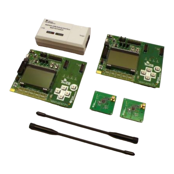
1. Kit Contents
2 x SmartRF™ Transciever EB (TrxEB)
2 x CC1120EM 868/915 MHz (EM)
2 x W5017 Pulse Antennas, ¼ wave, 2 dBi *
1 x MSP430 Debug Probe (FET)
2 x Micro USB Cables
1 x Standard USB Cable
1 x 14-pin Flat Cable
Documentation
The boards in this kit are designed to comply
with applicable ETSI, FCC and IC regulatory
requirements.
(* picture may deviate)
4. Select Board Mode
Use the switches S1 and S2 to select the
operating mode of the board. For the sake of this
quick start guide, please select "Enable" and
"UART". This configuration will make it possible
to communicate directly with the MSP430 over a
virtual COM port on the PC.
7. Welcome Screen
Turn on power with the Main Power switch. You
should now see the Texas Instruments logo and
a short description of the buttons on the LCD.
Pushing any of the five buttons on the board will
take you to the main menu.
NB! If you don't see anything on the screen
make sure the mode switches are in the
correct positions (see step 4 above).
2. TrxEB Overview
Power
EM
Board Mode
Selection
Breakout
Switches
Main
Power
Switch
USB
MSP430
Debug
Interface
MSP430
LCD
Breakout
5. Power Options
There are several ways of applying power to the
TrxEB.
2 x 1.5V AA Non-Rechargeable Alkaline
Batteries
USB (5V through USB plug)
External Power Supply (requirements below)
MSP430 Debugger
When the power source is batteries or USB, the
voltage regulators on the TrxEB will set the on-
board supply voltage to 3.3VDC.
i
External Power Supply
Requirements:
Nom Voltage: 3.3VDC
Max Current: 800 mA
Efficiency Level V
Warning! To minimize risk of personal injury or
property
damage,
never
batteries to power the board.
8. Packet Error Rate Test
Select the PER (Packet Error Rate) test by
highlighting the selection using the up/down
buttons. Confirm your selection by pressing
Enter (right button).
Web sites:
www.ti.com/lprf
E2E Forum:
www.ti.com/lprf-forum
3. Plug the EM into the TrxEB
EM
Connectors
Insert a CC1120EM board into the TrxEB as
shown above. Connect the antenna firmly to the
SMA connector on the EM.
Buttons
LEDs
6. Select Power Source
Depending on the power source, make sure you
connect jumpers to the appropriate pins on the
"Power Source" header. For instance, if you use
batteries, use a jumper to short-circuit pin 1 and
2 on the header. See back side of board for
explanation of the jumpers.
Note that there should only be one active
power source at any one time. Do not leave
use
rechargeable
the EVM powered when unattended.
9. Select Test Mode
The PER test can be run is several modes. Easy
Mode sets up a one-way test and uses default
settings. This test is convenient for practical
range testing.
The other test modes are described in the
"Software Examples for CC112x, CC11xL and
CC1101 User's Guide".
To proceed, highlight "Easy Mode" and press
Enter (right button).
Make sure to subscribe to the Low-Power RF
Newsletter to receive information about updates to
documentation, new product releases, and more.
Sign up on the TI web pages.
SWRU290B
December 2015
Caution!
The
kit
contains
ESD
sensitive components. Handle with
care to prevent permanent damage.
Advertisement
Table of Contents

Related Manuals for Texas Instruments CC1120


Summary of Contents for Texas Instruments CC1120
- Page 1 Select the PER (Packet Error Rate) test by The PER test can be run is several modes. Easy should now see the Texas Instruments logo and highlighting the selection using the up/down Mode sets up a one-way test and uses default a short description of the buttons on the LCD.
- Page 2 SmartRF Studio from Select the “Sub 1 GHz” tab and double click the run link tests with another CC1120 on a www.ti.com/smartrfstudio. highlighted CC1120 device icon. SmartRF TrxEB connected to the PC.
- Page 3 IMPORTANT NOTICE FOR TI DESIGN INFORMATION AND RESOURCES Texas Instruments Incorporated (‘TI”) technical, application or other design advice, services or information, including, but not limited to, reference designs and materials relating to evaluation modules, (collectively, “TI Resources”) are intended to assist designers who are developing applications that incorporate TI products;...
Need help?
Do you have a question about the CC1120 and is the answer not in the manual?
Questions and answers