Texas Instruments CC1110 Quick Start Manual
Mini development kit 868-915 mhz
Hide thumbs
Also See for CC1110:
- User manual (28 pages) ,
- Design manual (9 pages) ,
- Quick start instructions (3 pages)
Table of Contents
Advertisement
Quick Links
CC1110 Mini Development Kit 868-915 MHz
1 Kit Contents
The hardware in this kit is FCC/IC certified and complies with ETSI/R&TTE over temperature from 0 to +35°C.
2 Running the Preprogrammed Link Test
2.1 Introduction
The CC1110 on the SmartRFCC1110 target
board is preprogrammed with a link test which
operates at 868.3 MHz, and uses GFSK
modulation and a bit rate of 2.4 kbps.
The link test runs a point-to-point communication
between a Slave and a Master node based on
the SimpliciTI 1.1.0 protocol.
First the Master and Slave nodes must be
configured
as
described
in
sections. The two nodes will then establish a
link. When this link is established, the Master
starts to periodically send packets to the Slave.
Between each transmission, the Master goes to
receive mode and waits 250 ms for an
acknowledgement packet from the Slave. The
Slave node is in receive mode waiting for
packets from the Master. For each received
packet, the Slave automatically responds with
an acknowledgement packet.
2.4 Configure the Slave Node
On the other board, press the S2/SLAVE button
that is placed on the right side of the board.
When the button has been pushed, the two
LEDs on this board will blink very slowly until a
link with a Master node is established. Note that
establishing the link may finish in less than 1 s
depending on the environment.
It is important to keep distance (more than 1
meter) between the two nodes when they are
trying to establish the link to avoid saturation.
This is because full output power (12 dBm) is
used for this communication between the nodes.
Quick Start Guide
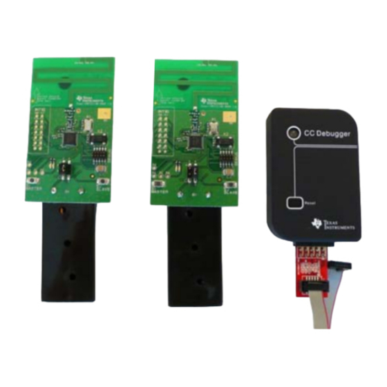
2 x SmartRFCC1110-868 target boards
1 x CC Debugger
1 x 10- pin flat cable with 2x5 2.54 mm connector
1 x 10-pin flat cable with 2x5 1.27 mm connector
1 x Converter board 2.54 mm – 1.27 mm connector
1 x Mini USB cable
Batteries
CD with Evaluation Version of the IAR EW8051
Documentation
2.2 Powering the boards
Place 2 AAA batteries in the battery holders
placed on the bottom side of each of the
SmartRFCC1110-868 boards. Place the jumper
on the power selection connector P1 between
pin 1 and pin 2 on each board.
the
following
Applying power to the SmartRFCC1110-868
starts the preprogrammed link test on the
CC1110 and the two LEDs on the board are on
for 1 s.
Warning! To minimize risk of personal
injury or property damage, never use
rechargeable batteries to power the board.
Do not leave the board powered when
unattended.
2.5 The LEDs on the Master Node
LEDs
Both
LEDs
blink rapidly
Green
LED
on for 0.5 s
Red LED on
for 0.5 s
Red LED on
for 3 s
Red LED on
for 5 s
2.3 Configure the Master Node
Press the S1/MASTER button that is placed on
the left hand side of the board. When this
button is pushed, the two LEDs on this board
will blink rapidly. The Master now waits for a
Slave node to establish a link.
Note that the boards only respond to the first
button push. To reconfigure the board, the
board must be reset, see point 2.9 in this
manual.
2.6 The LEDs on the Slave node
State
The Master is trying to
establish a link with a
Slave
The
Master
has
received an ACK to a
packet sent, link ok
The Master has not
received an ACK to the
last 3 packets sent
If the Master does not
receive ACKs from the
SLAVE in ~70 s, the
Master will stop to send
packets to save power.
Press S1/MASTER to
resume the link test
For test only:
When
the
link
is
established,
pressing
the S2/SLAVE button
turns the red LED on for
5 s
SWRU234b
October 2012
Caution! The kit contains ESD
sensitive
components.
Handle
with care to prevent permanent
damage. To minimize risk of
injury,
avoid
touching
components during operation if
symbolized as hot.
LEDs
State
The Slave is trying to
Both
LEDs
establish a link with a
blink slowly
Master
The link between the
Slave and Master is
Red LED on
established
and
continuously
Slave is in RX waiting
for packets from the
Master
Green
LED
The Slave has received
on for 0.5 s
a
packet
from
while red LED
Master and sent an
on
ACK, link ok
continuously
the
the
Advertisement
Table of Contents

Related Manuals for Texas Instruments CC1110


Summary of Contents for Texas Instruments CC1110
- Page 1 250 ms for an Note that the boards only respond to the first CC1110 and the two LEDs on the board are on acknowledgement packet from the Slave. The button push. To reconfigure the board, the for 1 s.
- Page 2 Embedded Workbench for 8051 from IAR Systems. Testing the radio performance of CC1110 using SmartRF Studio. SmartRF Studio can be used for RF testing, evaluation of CC1110 and to For more details, please refer to the CC Debugger User’s Guide find optimal register settings.
- Page 3 Any exceptions to this are strictly prohibited and unauthorized by Texas Instruments unless user has obtained appropriate experimental/development licenses from local regulatory authorities, which is responsibility of user including its acceptable authorization.
- Page 4 FCC Interference Statement for Class B EVM devices This equipment has been tested and found to comply with the limits for a Class B digital device, pursuant to part 15 of the FCC Rules. These limits are designed to provide reasonable protection against harmful interference in a residential installation. This equipment generates, uses and can radiate radio frequency energy and, if not installed and used in accordance with the instructions, may cause harmful interference to radio communications.
- Page 5 Also, please do not transfer this product, unless you give the same notice above to the transferee. Please note that if you could not follow the instructions above, you will be subject to penalties of Radio Law of Japan. Texas Instruments Japan Limited (address) 24-1, Nishi-Shinjuku 6 chome, Shinjuku-ku, Tokyo, Japan http://www.tij.co.jp...
- Page 6 FDA Class III or similar classification, then you must specifically notify TI of such intent and enter into a separate Assurance and Indemnity Agreement. Mailing Address: Texas Instruments, Post Office Box 655303, Dallas, Texas 75265 Copyright © 2012, Texas Instruments Incorporated...
Need help?
Do you have a question about the CC1110 and is the answer not in the manual?
Questions and answers