Table of Contents
Advertisement
Quick Links
ADS5294, 8-Channel, Analog-to-Digital Converter
This user's guide gives a general overview of the evaluation module (EVM) and provides a general
description of the features and functions to be considered while using this module. This manual is
applicable to the ADS5294 analog-to-digital converters (ADC), which collectively are referred to as
ADS529x. Use this document in combination with the respective ADC data sheet. The ADS529xEVM
provides a platform for evaluating the ADC under various signal, clock, reference, and power supply
conditions.
1
2
3
3.1
3.2
....................................................................................................................
4
5
6
7
8
8.1
9
9.1
9.2
9.3
9.4
10
11
12
1
2
3
4
5
6
7
8
9
10
11
12
13
Windows, Microsoft are trademarks of Microsoft Corporation.
SLAU355A - July 2011 - Revised March 2015
Submit Documentation Feedback
...........................................................................................
........................................................................................................
.......................................................................................
......................................................................................
..................................................................................
.........................................................................................................
......................................................................................................
.....................................................................................................
.............................................................................................................
.........................................................................................
........................................................................................................
..........................................................................................................
.............................................................................................
.......................................................................................
...........................................................................................................
...........................................................................................
............................................................................
.............................................................................................................
........................................................................................
........................................................................................................
......................................................................................................
.....................................................................................................
...........................................................................................
.....................................................................................................
....................................................................................
.......................................................................................
...........................................................................................
............................................................................................
ADS5294, 8-Channel, Analog-to-Digital Converter Evaluation Module
Copyright © 2011-2015, Texas Instruments Incorporated
SLAU355A - July 2011 - Revised March 2015
Evaluation Module
Contents
.........................................................................
...............................................
List of Figures
......................................................................
User's Guide
...........................................
3
4
5
5
5
6
7
8
11
12
15
17
17
19
21
22
23
31
33
41
3
4
7
8
9
11
12
13
14
16
17
19
21
1
Advertisement
Table of Contents

Related Manuals for Texas Instruments ADS5294


Summary of Contents for Texas Instruments ADS5294
-
Page 1: Table Of Contents
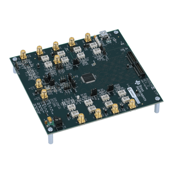
This manual is applicable to the ADS5294 analog-to-digital converters (ADC), which collectively are referred to as ADS529x. Use this document in combination with the respective ADC data sheet. The ADS529xEVM provides a platform for evaluating the ADC under various signal, clock, reference, and power supply conditions. - Page 2 Channel 8 Configuration ................ADC Clock Various Mode Jumper Settings ......................LED Indicators ....................Miscellaneous Test Points ADS5294, 8-Channel, Analog-to-Digital Converter Evaluation Module SLAU355A – July 2011 – Revised March 2015 Submit Documentation Feedback Copyright © 2011–2015, Texas Instruments Incorporated...
-
Page 3: Quick View Of Evaluation Setup
(optional) paths to attenuate the harmonics and noise from the generators. Power Supply: A single +5-V supply powers the ADS5294EVM. The supplies for the ADS5294 device are derived from the +5-V supply. The power supply must be able to source up to 1.5 A. A +6-V supply can power the TSW1400EVM using a wall adapter. -
Page 4: Default Configuration
2. P1: +5-V Power supplies the connector. 3. JP4, JP5, and JP6 are set to enable +3.3V Analog, +1.8VD Digital, and +1.8VA Analog to device, ADS5294, 8-Channel, Analog-to-Digital Converter Evaluation Module SLAU355A – July 2011 – Revised March 2015 Submit Documentation Feedback... -
Page 5: Software Installation And Operation
4. JP13: Enable onboard CMOS clock. 5. JP16, JP18, JP19, JP20: ADC clock source selection jumpers. Software Installation and Operation The ADS5294EVM comes with a software install. To Dowload the software, visit the ADS5294 product folder under Tools & software . -
Page 6: Test Setup
Continue Anyway to continue with the installation. If Windows XP is configured to ignore file signature warnings, no message appears. Test Setup To evaluate the ADS5294 device, a TSW1400EVM is required. Figure 3 shows the exact setup of these two boards and external connectors. -
Page 7: Power Up Ads5294
Three green LEDs and one orange LED turned on as shown in Figure 4 (also see Figure 13). SLAU355A – July 2011 – Revised March 2015 ADS5294, 8-Channel, Analog-to-Digital Converter Evaluation Module Submit Documentation Feedback Copyright © 2011–2015, Texas Instruments Incorporated... -
Page 8: Launch Ads5294 Gui
Launch ADS5294 GUI www.ti.com Figure 4. Power-Up Indications Launch ADS5294 GUI After launching the ADS5294 GUI, the GUI appears as is shown in Figure 5. After the GUI is completely launched, the window appears as is displayed in Figure 5. Select the Top Level tab to observe the default condition. -
Page 9: Ads5294 Gui Launch
Launch ADS5294 GUI www.ti.com Figure 5. ADS5294 GUI Launch SLAU355A – July 2011 – Revised March 2015 ADS5294, 8-Channel, Analog-to-Digital Converter Evaluation Module Submit Documentation Feedback Copyright © 2011–2015, Texas Instruments Incorporated... - Page 10 ADC output interface in 2-WIRE LVDS mode. Also click button ADC Bit Resolution to set ADC in 14 Bits mode. Ensure that the MSB_LSB button status shows LSB_First. ADS5294, 8-Channel, Analog-to-Digital Converter Evaluation Module SLAU355A – July 2011 – Revised March 2015 Submit Documentation Feedback Copyright ©...
-
Page 11: Launch Tsw1400 Gui
3. ADC Input Frequency – enter 5M and the GUI calculates the real coherent frequency (Fc) to 4.99633789M. Figure 6. TSW1400 GUI Launch SLAU355A – July 2011 – Revised March 2015 ADS5294, 8-Channel, Analog-to-Digital Converter Evaluation Module Submit Documentation Feedback Copyright © 2011–2015, Texas Instruments Incorporated... -
Page 12: Test Ads5294
TEST ADS5294 Step 1: Time Domain • Select Time Domain page from TSW1400 GUI. Figure 7. ADS5294 Time Domain Setup ADS5294, 8-Channel, Analog-to-Digital Converter Evaluation Module SLAU355A – July 2011 – Revised March 2015 Submit Documentation Feedback Copyright © 2011–2015, Texas Instruments Incorporated... -
Page 13: Ads5294 Test Pattern
TI FAE (Field Application Engineer) to troubleshoot the problem. • On the ADS5294 GUI, change Test Pattern to None from RAMP PATTERN for next step. SLAU355A – July 2011 – Revised March 2015 ADS5294, 8-Channel, Analog-to-Digital Converter Evaluation Module Submit Documentation Feedback Copyright ©... -
Page 14: User Interface: Time Domain Format
TEST ADS5294 www.ti.com Figure 9. User Interface: Time Domain Format ADS5294, 8-Channel, Analog-to-Digital Converter Evaluation Module SLAU355A – July 2011 – Revised March 2015 Submit Documentation Feedback Copyright © 2011–2015, Texas Instruments Incorporated... -
Page 15: Step 2: Single Tone Fft
• Press Capture button to get the test result. • Repeat for Channel 2...Channel 8. SLAU355A – July 2011 – Revised March 2015 ADS5294, 8-Channel, Analog-to-Digital Converter Evaluation Module Submit Documentation Feedback Copyright © 2011–2015, Texas Instruments Incorporated... -
Page 16: User Interface: Single Fft Format
TEST ADS5294 www.ti.com Figure 10. User Interface: Single FFT Format ADS5294, 8-Channel, Analog-to-Digital Converter Evaluation Module SLAU355A – July 2011 – Revised March 2015 Submit Documentation Feedback Copyright © 2011–2015, Texas Instruments Incorporated... -
Page 17: Board Configuration
TP1, TP2, TP3, Ground test points. TP4, TP5, TP14, TP21, TP23, TP25, TP34, USB1 USB interface connector SLAU355A – July 2011 – Revised March 2015 ADS5294, 8-Channel, Analog-to-Digital Converter Evaluation Module Submit Documentation Feedback Copyright © 2011–2015, Texas Instruments Incorporated... - Page 18 Default) R170) and remove two resistors(R171 and R172) from J6.It uses TI THS4509 single-ended to differential amplifier. ADS5294, 8-Channel, Analog-to-Digital Converter Evaluation Module SLAU355A – July 2011 – Revised March 2015 Submit Documentation Feedback Copyright © 2011–2015, Texas Instruments Incorporated...
-
Page 19: Adc Clock
J8, JP19, JP20, JP16, JP20 (2-3), JP19 (2-3), JP16 (2-3), JP18 (2-3) Dia. 2 Clock Generator JP18 and Connect CMOS clock generator output at SMA connector J8. SLAU355A – July 2011 – Revised March 2015 ADS5294, 8-Channel, Analog-to-Digital Converter Evaluation Module Submit Documentation Feedback Copyright © 2011–2015, Texas Instruments Incorporated... - Page 20 CMOS generator output at SMA connector J8. This configures the external CMOS source as clock input to buffer. Dia.1 Dia.2 Dia.3 Dia.4 Dia.5 ADS5294, 8-Channel, Analog-to-Digital Converter Evaluation Module SLAU355A – July 2011 – Revised March 2015 Submit Documentation Feedback Copyright © 2011–2015, Texas Instruments Incorporated...
-
Page 21: Light-Emitting Diodes
Color LED_+5V +5 V Green LED1.8VA +1.8 VA Green LED1.8VD +1.8 VD Green LED3.3VA +3.3 VA Orange SLAU355A – July 2011 – Revised March 2015 ADS5294, 8-Channel, Analog-to-Digital Converter Evaluation Module Submit Documentation Feedback Copyright © 2011–2015, Texas Instruments Incorporated... -
Page 22: Miscellaneous Test Points
RESET: Install to reset the device (DUT1) manually JP12 PD: Install to power down the device (DUT1) manually ADS5294, 8-Channel, Analog-to-Digital Converter Evaluation Module SLAU355A – July 2011 – Revised March 2015 Submit Documentation Feedback Copyright © 2011–2015, Texas Instruments Incorporated... -
Page 23: Evm Schematics
EVM Schematics www.ti.com EVM Schematics Figure 15. Schematic, Sheet 1 of 9 SLAU355A – July 2011 – Revised March 2015 ADS5294, 8-Channel, Analog-to-Digital Converter Evaluation Module Submit Documentation Feedback Copyright © 2011–2015, Texas Instruments Incorporated... - Page 24 EVM Schematics www.ti.com Figure 16. Schematic, Sheet 2 of 9 Figure 17. Schematic, Sheet 3 of 9 ADS5294, 8-Channel, Analog-to-Digital Converter Evaluation Module SLAU355A – July 2011 – Revised March 2015 Submit Documentation Feedback Copyright © 2011–2015, Texas Instruments Incorporated...
- Page 25 EVM Schematics www.ti.com Figure 18. Schematic, Sheet 4 of 9 SLAU355A – July 2011 – Revised March 2015 ADS5294, 8-Channel, Analog-to-Digital Converter Evaluation Module Submit Documentation Feedback Copyright © 2011–2015, Texas Instruments Incorporated...
- Page 26 EVM Schematics www.ti.com Figure 19. Schematic, Sheet 5 of 9 ADS5294, 8-Channel, Analog-to-Digital Converter Evaluation Module SLAU355A – July 2011 – Revised March 2015 Submit Documentation Feedback Copyright © 2011–2015, Texas Instruments Incorporated...
- Page 27 EVM Schematics www.ti.com Figure 20. Schematic, Sheet 6 of 9 SLAU355A – July 2011 – Revised March 2015 ADS5294, 8-Channel, Analog-to-Digital Converter Evaluation Module Submit Documentation Feedback Copyright © 2011–2015, Texas Instruments Incorporated...
- Page 28 EVM Schematics www.ti.com Figure 21. Schematic, Sheet 7 of 9 ADS5294, 8-Channel, Analog-to-Digital Converter Evaluation Module SLAU355A – July 2011 – Revised March 2015 Submit Documentation Feedback Copyright © 2011–2015, Texas Instruments Incorporated...
- Page 29 EVM Schematics www.ti.com Figure 22. Schematic, Sheet 8 of 9 SLAU355A – July 2011 – Revised March 2015 ADS5294, 8-Channel, Analog-to-Digital Converter Evaluation Module Submit Documentation Feedback Copyright © 2011–2015, Texas Instruments Incorporated...
- Page 30 EVM Schematics www.ti.com Figure 23. Schematic, Sheet 9 of 9 ADS5294, 8-Channel, Analog-to-Digital Converter Evaluation Module SLAU355A – July 2011 – Revised March 2015 Submit Documentation Feedback Copyright © 2011–2015, Texas Instruments Incorporated...
-
Page 31: Ads5294Evm Bill Of Materials
CAPACITOR, SMT, 0603, CERAMIC, 10µF, 10 µF Taiyo Yuden C33, C51, C54 6.3V, 20%, X5R JUMPER-0603(UN) UNINSTALLED JUMPER, SMT0603 TP8–TP11, TP15–TP20 SLAU355A – July 2011 – Revised March 2015 ADS5294, 8-Channel, Analog-to-Digital Converter Evaluation Module Submit Documentation Feedback Copyright © 2011–2015, Texas Instruments Incorporated... - Page 32 STANDOFF HEX M3 THR ALUM 18MM 29311 SCREW STEEL M3 THR 6MM SCREW Keystone SCREW STEEL M3 THR 6MM ADS5294, 8-Channel, Analog-to-Digital Converter Evaluation Module SLAU355A – July 2011 – Revised March 2015 Submit Documentation Feedback Copyright © 2011–2015, Texas Instruments Incorporated...
-
Page 33: Ads5294Evm Printed-Circuit Board Layout
XTAL LED_+5V TP_VP S/N: -2.5V +2.5V JP21 Figure 24. ADS5294EVM Top Layer Assembly Drawing – Top View SLAU355A – July 2011 – Revised March 2015 ADS5294, 8-Channel, Analog-to-Digital Converter Evaluation Module Submit Documentation Feedback Copyright © 2011–2015, Texas Instruments Incorporated... - Page 34 JP11 JP15 JP17 JP20 JP13 JP19 JP21 Figure 25. ADS5294EVM Bottom Layer Assembly Drawing – Bottom View ADS5294, 8-Channel, Analog-to-Digital Converter Evaluation Module SLAU355A – July 2011 – Revised March 2015 Submit Documentation Feedback Copyright © 2011–2015, Texas Instruments Incorporated...
- Page 35 ADS5294EVM Printed-Circuit Board Layout www.ti.com Figure 26. ADS5294EVM Top Layer Copper – Top View SLAU355A – July 2011 – Revised March 2015 ADS5294, 8-Channel, Analog-to-Digital Converter Evaluation Module Submit Documentation Feedback Copyright © 2011–2015, Texas Instruments Incorporated...
- Page 36 ADS5294EVM Printed-Circuit Board Layout www.ti.com Figure 27. ADS5294EVM Internal Layer 1, Ground – Top View ADS5294, 8-Channel, Analog-to-Digital Converter Evaluation Module SLAU355A – July 2011 – Revised March 2015 Submit Documentation Feedback Copyright © 2011–2015, Texas Instruments Incorporated...
- Page 37 ADS5294EVM Printed-Circuit Board Layout www.ti.com Figure 28. ADS5294EVM Internal Layer 2, Power – Top View SLAU355A – July 2011 – Revised March 2015 ADS5294, 8-Channel, Analog-to-Digital Converter Evaluation Module Submit Documentation Feedback Copyright © 2011–2015, Texas Instruments Incorporated...
- Page 38 ADS5294EVM Printed-Circuit Board Layout www.ti.com Figure 29. ADS5294EVM Internal Layer 3, Power – Top View ADS5294, 8-Channel, Analog-to-Digital Converter Evaluation Module SLAU355A – July 2011 – Revised March 2015 Submit Documentation Feedback Copyright © 2011–2015, Texas Instruments Incorporated...
- Page 39 ADS5294EVM Printed-Circuit Board Layout www.ti.com Figure 30. ADS5294EVM Internal Layer 4, Ground – Top View SLAU355A – July 2011 – Revised March 2015 ADS5294, 8-Channel, Analog-to-Digital Converter Evaluation Module Submit Documentation Feedback Copyright © 2011–2015, Texas Instruments Incorporated...
- Page 40 ADS5294EVM Printed-Circuit Board Layout www.ti.com Figure 31. ADS5294EVM Bottom Layer Copper – Top View ADS5294, 8-Channel, Analog-to-Digital Converter Evaluation Module SLAU355A – July 2011 – Revised March 2015 Submit Documentation Feedback Copyright © 2011–2015, Texas Instruments Incorporated...
-
Page 41: Appendix A High Speed Data Converter Pro (Hsdcpro) Gui Installation
Leave the destination directories as the default location, for the TSW1400GUI installation and press the NEXT button as shown in Figure SLAU355A – July 2011 – Revised March 2015 High Speed Data Converter Pro (HSDCPro) GUI Installation Submit Documentation Feedback Copyright © 2011–2015, Texas Instruments Incorporated... - Page 42 Appendix A www.ti.com Figure 33. HSDCPro Install (Install Directory) • Read the License Agreement from Texas Instruments and select I accept the License Agreement and press the Next button as shown in Figure High Speed Data Converter Pro (HSDCPro) GUI Installation SLAU355A –...
- Page 43 Read the License Agreement from National Instruments and select I accept the License Agreement and press the Next button as shown in Figure SLAU355A – July 2011 – Revised March 2015 High Speed Data Converter Pro (HSDCPro) GUI Installation Submit Documentation Feedback Copyright © 2011–2015, Texas Instruments Incorporated...
- Page 44 Figure 35. HSDCPro Install (NI License Agreement) • Press the Next button as shown in Figure High Speed Data Converter Pro (HSDCPro) GUI Installation SLAU355A – July 2011 – Revised March 2015 Submit Documentation Feedback Copyright © 2011–2015, Texas Instruments Incorporated...
- Page 45 The window shown in Figure 37 should appear indicating that the installation is in progress. SLAU355A – July 2011 – Revised March 2015 High Speed Data Converter Pro (HSDCPro) GUI Installation Submit Documentation Feedback Copyright © 2011–2015, Texas Instruments Incorporated...
- Page 46 • The window shown in Figure 38 appears indicating Installation Complete. Press the Next button. High Speed Data Converter Pro (HSDCPro) GUI Installation SLAU355A – July 2011 – Revised March 2015 Submit Documentation Feedback Copyright © 2011–2015, Texas Instruments Incorporated...
- Page 47 Figure 38. HSDCPro Install (Installation Complete) • The window shown in Figure 39 appears briefly to complete the process. SLAU355A – July 2011 – Revised March 2015 High Speed Data Converter Pro (HSDCPro) GUI Installation Submit Documentation Feedback Copyright © 2011–2015, Texas Instruments Incorporated...
- Page 48 National Instruments MCR Installer. If requested, hit the Restart button to complete the installation. Figure 40. HSDCPro Install High Speed Data Converter Pro (HSDCPro) GUI Installation SLAU355A – July 2011 – Revised March 2015 Submit Documentation Feedback Copyright © 2011–2015, Texas Instruments Incorporated...
- Page 49 Added Appendix A: High Speed Data Converter Pro (HSDCPro) GUI Installation. NOTE: Page numbers for previous revisions may differ from page numbers in the current version. SLAU355A – July 2011 – Revised March 2015 Revision History Submit Documentation Feedback Copyright © 2011–2015, Texas Instruments Incorporated...
- Page 50 STANDARD TERMS AND CONDITIONS FOR EVALUATION MODULES Delivery: TI delivers TI evaluation boards, kits, or modules, including any accompanying demonstration software, components, or documentation (collectively, an “EVM” or “EVMs”) to the User (“User”) in accordance with the terms and conditions set forth herein. Acceptance of the EVM is expressly subject to the following terms and conditions.
- Page 51 FCC Interference Statement for Class B EVM devices NOTE: This equipment has been tested and found to comply with the limits for a Class B digital device, pursuant to part 15 of the FCC Rules. These limits are designed to provide reasonable protection against harmful interference in a residential installation.
- Page 52 【無線電波を送信する製品の開発キットをお使いになる際の注意事項】 本開発キットは技術基準適合証明を受けておりません。 本製品のご使用に際しては、電波法遵守のため、以下のいずれかの措置を取っていただく必要がありますのでご注意ください。 1. 電波法施行規則第6条第1項第1号に基づく平成18年3月28日総務省告示第173号で定められた電波暗室等の試験設備でご使用 いただく。 2. 実験局の免許を取得後ご使用いただく。 3. 技術基準適合証明を取得後ご使用いただく。 なお、本製品は、上記の「ご使用にあたっての注意」を譲渡先、移転先に通知しない限り、譲渡、移転できないものとします。 上記を遵守頂けない場合は、電波法の罰則が適用される可能性があることをご留意ください。 日本テキサス・インスツルメンツ株式会社 東京都新宿区西新宿6丁目24番1号 西新宿三井ビル 3.3.3 Notice for EVMs for Power Line Communication: Please see http://www.tij.co.jp/lsds/ti_ja/general/eStore/notice_02.page 電力線搬送波通信についての開発キットをお使いになる際の注意事項については、次のところをご覧くださ い。http://www.tij.co.jp/lsds/ti_ja/general/eStore/notice_02.page SPACER EVM Use Restrictions and Warnings: 4.1 EVMS ARE NOT FOR USE IN FUNCTIONAL SAFETY AND/OR SAFETY CRITICAL EVALUATIONS, INCLUDING BUT NOT LIMITED TO EVALUATIONS OF LIFE SUPPORT APPLICATIONS.
- Page 53 Notwithstanding the foregoing, any judgment may be enforced in any United States or foreign court, and TI may seek injunctive relief in any United States or foreign court. Mailing Address: Texas Instruments, Post Office Box 655303, Dallas, Texas 75265 Copyright © 2015, Texas Instruments Incorporated...
- Page 54 IMPORTANT NOTICE Texas Instruments Incorporated and its subsidiaries (TI) reserve the right to make corrections, enhancements, improvements and other changes to its semiconductor products and services per JESD46, latest issue, and to discontinue any product or service per JESD48, latest issue.
Need help?
Do you have a question about the ADS5294 and is the answer not in the manual?
Questions and answers