Table of Contents
Advertisement
Quick Links
ADS5295, 8-Channel, Analog-to-Digital Converter
This user's guide gives a general overview of the evaluation module (EVM) and provides a general
description of the features and functions to be considered while using this module. This manual is
applicable to the ADS5295 analog-to-digital converters (ADC), which, with the ADS5292 and ADS5294,
are collectively referred to as ADS529x. Use this document in combination with the respective ADC data
sheet. The ADS529xEVM provides a platform for evaluating the ADC under various signal, clock,
reference, and power supply conditions.
1
2
3
3.1
..................................................................................................................
4
5
6
7
8
8.1
8.2
9
9.1
9.2
9.3
9.4
10
11
12
1
2
3
4
5
6
7
ADS5295 GUI Plug-In Tab
8
9
10
11
12
13
14
SLAU442 - November 2012
Submit Documentation Feedback
...........................................................................................
.......................................................................................................
......................................................................................
.....................................................................................
.......................................................................................................
...............................................................................................
.............................................................................................................
............................................................................................
........................................................................................
.......................................................................................................
.........................................................................................................
...................................................................................
.......................................................................................
..........................................................................................................
..........................................................................................
............................................................................................................
.......................................................................................
.....................................................................................................
..............................................................................................................
...............................................................................................
..............................................................................................................
...........................................................................................
.........................................................................................................
.................................................................................
...................................................................................................
.............................................................................................
..................................................................................................
ADS5295, 8-Channel, Analog-to-Digital Converter Evaluation Module
Copyright © 2012, Texas Instruments Incorporated
Evaluation Module
Contents
.............................................................
........................................................................
...........................................................................
List of Figures
..............................................................
.........................................................................
User's Guide
SLAU442 - November 2012
3
4
5
5
12
13
14
17
20
20
26
29
29
31
33
34
36
45
47
3
4
12
13
14
16
17
18
20
21
22
23
24
25
1
Advertisement
Table of Contents

Subscribe to Our Youtube Channel
Related Manuals for Texas Instruments ADS5295


Summary of Contents for Texas Instruments ADS5295
-
Page 1: Table Of Contents
This manual is applicable to the ADS5295 analog-to-digital converters (ADC), which, with the ADS5292 and ADS5294, are collectively referred to as ADS529x. Use this document in combination with the respective ADC data sheet. - Page 2 Channel 8 Configuration ................ADC Clock Various Mode Jumper Settings ......................LED Indicators ....................Miscellaneous Test Points ......................Bill of Materials ADS5295, 8-Channel, Analog-to-Digital Converter Evaluation Module SLAU442 – November 2012 Submit Documentation Feedback Copyright © 2012, Texas Instruments Incorporated...
-
Page 3: Quick View Of Evaluation Setup
(optional) paths to attenuate the harmonics and noise from the generators. Power Supply: A single +5-V supply powers the EVM. The supplies for the ADS5295 device are derived from the +5-V supply. The power supply must be able to source up to 1.5 A. A +5-V wall adapter supply powers the TSW1400EVM. -
Page 4: Default Configuration
3. JP4, JP5, and JP6 are set to enable +3.3V analog, +1.8VD digital, and +1.8VA analog to device, respectively. 4. JP13: Enable onboard CMOS clock. 5. JP16, JP18, JP19, JP20: ADC clock source selection jumpers. ADS5295, 8-Channel, Analog-to-Digital Converter Evaluation Module SLAU442 – November 2012 Submit Documentation Feedback Copyright © 2012, Texas Instruments Incorporated... -
Page 5: Software Installation And Operation
The EVM requires a software installation to invoke the GUI. In addition, the TSW1400 High Speed Data Converter Pro GUI (version 2.0 or higher) must be installed. The following section describes the installation procedure for the ADS5295 GUI. For instructions on installing the TSW1400 High Speed Data Converter Pro GUI, please visit the TI website. - Page 6 Software Installation and Operation www.ti.com • Click Next. ADS5295, 8-Channel, Analog-to-Digital Converter Evaluation Module SLAU442 – November 2012 Submit Documentation Feedback Copyright © 2012, Texas Instruments Incorporated...
- Page 7 Software Installation and Operation www.ti.com • Click Next to proceed with the default install paths or Browse to desired paths and then click Next. SLAU442 – November 2012 ADS5295, 8-Channel, Analog-to-Digital Converter Evaluation Module Submit Documentation Feedback Copyright © 2012, Texas Instruments Incorporated...
- Page 8 Software Installation and Operation www.ti.com • Read the Software License Agreement and click I accept... and then click Next. ADS5295, 8-Channel, Analog-to-Digital Converter Evaluation Module SLAU442 – November 2012 Submit Documentation Feedback Copyright © 2012, Texas Instruments Incorporated...
- Page 9 Software Installation and Operation www.ti.com • Click Next to begin installation of listed components. SLAU442 – November 2012 ADS5295, 8-Channel, Analog-to-Digital Converter Evaluation Module Submit Documentation Feedback Copyright © 2012, Texas Instruments Incorporated...
- Page 10 Software Installation and Operation www.ti.com • The following window shows the installation progress: ADS5295, 8-Channel, Analog-to-Digital Converter Evaluation Module SLAU442 – November 2012 Submit Documentation Feedback Copyright © 2012, Texas Instruments Incorporated...
- Page 11 Software Installation and Operation www.ti.com • Clicking Finish completes the installation. • The PC must be restarted to complete the installation. SLAU442 – November 2012 ADS5295, 8-Channel, Analog-to-Digital Converter Evaluation Module Submit Documentation Feedback Copyright © 2012, Texas Instruments Incorporated...
-
Page 12: Test Setup
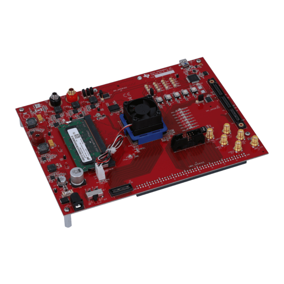
Test Setup www.ti.com Test Setup To evaluate the ADS5295 device, a TSW1400EVM is required. Figure 3 shows the exact setup of these two boards and external connectors. • Connect the P10 connector of the ADS5295EVM to the J3 connector of the TSW1400EVM. -
Page 13: Power Up Ads5295
LED (LED_+5V) and one orange LED (LED33VA) should turn on as shown in Figure 4 (also see Figure 20). Figure 4. Power-Up Indications SLAU442 – November 2012 ADS5295, 8-Channel, Analog-to-Digital Converter Evaluation Module Submit Documentation Feedback Copyright © 2012, Texas Instruments Incorporated... -
Page 14: Launch Tsw1400 High Speed Data Converter Pro Gui
TSW1400EVM that is connected and reports its serial number as shown in Figure • Clicking OK connects to the board. Figure 5. High Speed Data Converter Pro GUI Launch ADS5295, 8-Channel, Analog-to-Digital Converter Evaluation Module SLAU442 – November 2012 Submit Documentation Feedback Copyright © 2012, Texas Instruments Incorporated... - Page 15 Launch TSW1400 High Speed Data Converter Pro GUI www.ti.com • In the upper left corner of the GUI, select ADS5295 in the drop down menu of Select ADC. • Click Yes to update the Firmware for the ADC. SLAU442 – November 2012...
-
Page 16: Ads5295 Gui
• The following window appears while the firmware is loading. • A new tab labeled ADS5295 GUI appears in the High Speed Data Converter Pro GUI as shown in Figure 6. This tab allows control of the ADS5295 device. Figure 6. ADS5295 GUI ADS5295, 8-Channel, Analog-to-Digital Converter Evaluation Module SLAU442 –... -
Page 17: Ads5295 Gui Plug-In Tab
ADS5295 GUI Plug-In Tab www.ti.com ADS5295 GUI Plug-In Tab The third tab of the High Speed Data Converter Pro GUI labeled ADS5295 GUI contains all the serial register programming of the ADS5295 device. • The ADS5295 GUI tab contains two sub-tabs called Read Me First and High Level Test. The default... -
Page 18: Top Level Tab
The CUSTOM WRITE/READ section allows manual programming of a serial register's data value given it's address. In addition, the current data value of any serial register can be read from the device by inputting it's address. ADS5295, 8-Channel, Analog-to-Digital Converter Evaluation Module SLAU442 – November 2012 Submit Documentation Feedback... - Page 19 ADS5295 GUI Plug-In Tab www.ti.com SLAU442 – November 2012 ADS5295, 8-Channel, Analog-to-Digital Converter Evaluation Module Submit Documentation Feedback Copyright © 2012, Texas Instruments Incorporated...
-
Page 20: Test Ads5295
Test ADS5295 This section describes how to test the ADS5295 device in two ways: Time Domain and Single Tone. Step 1: Time Domain Time Domain test consists of applying a RAMP function to the ADC inputs, capturing, and verifying that every ADC code is generated incrementally. -
Page 21: Time Domain Test
Selection drop down menu as shown in Figure Figure 10. Time Domain Test • Input the appropriate ADC Sampling Rate (80 MHz in the default configuration of ADS5295 EVM) . • Press the Capture button. SLAU442 – November 2012 ADS5295, 8-Channel, Analog-to-Digital Converter Evaluation Module Submit Documentation Feedback Copyright ©... -
Page 22: Ads5295 Ramp Test Pattern Capture
Test ADS5295 www.ti.com • A saw tooth ramp should be captured as shown below. Figure 11. ADS5295 RAMP Test Pattern Capture ADS5295, 8-Channel, Analog-to-Digital Converter Evaluation Module SLAU442 – November 2012 Submit Documentation Feedback Copyright © 2012, Texas Instruments Incorporated... -
Page 23: Graph Zoom Functions
Use the zoom functions provided in the High Speed Data Converter Pro GUI to verify that the captured RAMP is correct. Figure 12. Graph Zoom Functions SLAU442 – November 2012 ADS5295, 8-Channel, Analog-to-Digital Converter Evaluation Module Submit Documentation Feedback Copyright © 2012, Texas Instruments Incorporated... -
Page 24: Ads5295 Ramp Verification
Zoom in on the RAMP until it is clear that every subsequent sample is an increment in ADC code as shown below. Figure 13. ADS5295 RAMP Verification ADS5295, 8-Channel, Analog-to-Digital Converter Evaluation Module SLAU442 – November 2012 Submit Documentation Feedback... -
Page 25: Adc Channel Selection
Repeat the above procedure for all eight ADC channels using the selection box shown in Figure Figure 14. ADC Channel Selection SLAU442 – November 2012 ADS5295, 8-Channel, Analog-to-Digital Converter Evaluation Module Submit Documentation Feedback Copyright © 2012, Texas Instruments Incorporated... -
Page 26: Step 2: Single Tone Fft
• Disable the RAMP PATTERN by setting the Enable Pattern Mode to None. Figure 15. Disable RAMP PATTERN ADS5295, 8-Channel, Analog-to-Digital Converter Evaluation Module SLAU442 – November 2012 Submit Documentation Feedback Copyright © 2012, Texas Instruments Incorporated... - Page 27 Auto Calculation box is checked) . • Check the box labeled Auto Calculation of Coherent Frequencies. Figure 16. Single Tone Test SLAU442 – November 2012 ADS5295, 8-Channel, Analog-to-Digital Converter Evaluation Module Submit Documentation Feedback Copyright © 2012, Texas Instruments Incorporated...
- Page 28 • Pressing the Capture button returns the test result. • Repeat for Channels 2 through 8. Figure 17. Single Tone Capture ADS5295, 8-Channel, Analog-to-Digital Converter Evaluation Module SLAU442 – November 2012 Submit Documentation Feedback Copyright © 2012, Texas Instruments Incorporated...
-
Page 29: Board Configuration
1.8 V. Onboard 1.8-V Analog enables. Set up as shown in Figure 2 is required to use onboard 1.8 V. SLAU442 – November 2012 ADS5295, 8-Channel, Analog-to-Digital Converter Evaluation Module Submit Documentation Feedback Copyright © 2012, Texas Instruments Incorporated... - Page 30 It is an alternative input for channel 8. Need to install two resistors (R169 and Default) R170) and remove two resistors(R171 and R172) from J6.It uses TI THS4509 single-ended to differential amplifier. ADS5295, 8-Channel, Analog-to-Digital Converter Evaluation Module SLAU442 – November 2012 Submit Documentation Feedback Copyright © 2012, Texas Instruments Incorporated...
-
Page 31: Adc Clock
In Figure 19, the EVM uses an onboard, single-ended clock as the default option. Figure 19. ADS5295EVM Default Clock Jumper Locations SLAU442 – November 2012 ADS5295, 8-Channel, Analog-to-Digital Converter Evaluation Module Submit Documentation Feedback Copyright © 2012, Texas Instruments Incorporated... - Page 32 CMOS generator output at SMA connector J8. This configures the external CMOS source as clock input to buffer. Dia.1 Dia.2 Dia.3 Dia.4 Dia.5 ADS5295, 8-Channel, Analog-to-Digital Converter Evaluation Module SLAU442 – November 2012 Submit Documentation Feedback Copyright © 2012, Texas Instruments Incorporated...
-
Page 33: Light-Emitting Diodes (Leds)
Table 4. LED Indicators Reference Designator Power Supply Color LED_+5V +5 V Green LED1.8VA +1.8 VA LED1.8VD +1.8 VD LED3.3VA +3.3 VA Orange SLAU442 – November 2012 ADS5295, 8-Channel, Analog-to-Digital Converter Evaluation Module Submit Documentation Feedback Copyright © 2012, Texas Instruments Incorporated... -
Page 34: Miscellaneous Test Points
TP_D0 SCLK: Serial clock input TP_D1 SDA: Serial data input TP_D2 SEN: Serial enable chip select TP_D7 SDOUT: Serial data output ADS5295, 8-Channel, Analog-to-Digital Converter Evaluation Module SLAU442 – November 2012 Submit Documentation Feedback Copyright © 2012, Texas Instruments Incorporated... - Page 35 Reference Designator Description JP14 RESET: Install to reset the device (DUT1) manually JP12 PD: Install to power down the device (DUT1) manually SLAU442 – November 2012 ADS5295, 8-Channel, Analog-to-Digital Converter Evaluation Module Submit Documentation Feedback Copyright © 2012, Texas Instruments Incorporated...
-
Page 36: Evm Schematics
EVM Schematics www.ti.com EVM Schematics Figure 22. Schematic, Sheet 1 of 9 ADS5295, 8-Channel, Analog-to-Digital Converter Evaluation Module SLAU442 – November 2012 Submit Documentation Feedback Copyright © 2012, Texas Instruments Incorporated... - Page 37 EVM Schematics www.ti.com Figure 23. Schematic, Sheet 2 of 9 SLAU442 – November 2012 ADS5295, 8-Channel, Analog-to-Digital Converter Evaluation Module Submit Documentation Feedback Copyright © 2012, Texas Instruments Incorporated...
- Page 38 EVM Schematics www.ti.com Figure 24. Schematic, Sheet 3 of 9 ADS5295, 8-Channel, Analog-to-Digital Converter Evaluation Module SLAU442 – November 2012 Submit Documentation Feedback Copyright © 2012, Texas Instruments Incorporated...
- Page 39 EVM Schematics www.ti.com Figure 25. Schematic, Sheet 4 of 9 SLAU442 – November 2012 ADS5295, 8-Channel, Analog-to-Digital Converter Evaluation Module Submit Documentation Feedback Copyright © 2012, Texas Instruments Incorporated...
- Page 40 EVM Schematics www.ti.com Figure 26. Schematic, Sheet 5 of 9 ADS5295, 8-Channel, Analog-to-Digital Converter Evaluation Module SLAU442 – November 2012 Submit Documentation Feedback Copyright © 2012, Texas Instruments Incorporated...
- Page 41 EVM Schematics www.ti.com Figure 27. Schematic, Sheet 6 of 9 SLAU442 – November 2012 ADS5295, 8-Channel, Analog-to-Digital Converter Evaluation Module Submit Documentation Feedback Copyright © 2012, Texas Instruments Incorporated...
- Page 42 EVM Schematics www.ti.com Figure 28. Schematic, Sheet 7 of 9 ADS5295, 8-Channel, Analog-to-Digital Converter Evaluation Module SLAU442 – November 2012 Submit Documentation Feedback Copyright © 2012, Texas Instruments Incorporated...
- Page 43 EVM Schematics www.ti.com Figure 29. Schematic, Sheet 8 of 9 SLAU442 – November 2012 ADS5295, 8-Channel, Analog-to-Digital Converter Evaluation Module Submit Documentation Feedback Copyright © 2012, Texas Instruments Incorporated...
- Page 44 EVM Schematics www.ti.com Figure 30. Schematic, Sheet 9 of 9 ADS5295, 8-Channel, Analog-to-Digital Converter Evaluation Module SLAU442 – November 2012 Submit Documentation Feedback Copyright © 2012, Texas Instruments Incorporated...
-
Page 45: Ads5295Evm Bill Of Materials
CAP CER 3.3PF 50V C0G 0402 3.3pF Murata C77,C85,C92,C99,C106,C113,C120,C127,C134 490-1270-1-ND GRM1555C1H6R8DZ0 CAP CER 6.8PF 50V C0G 0402 6.8pF Murata C77,C85,C92,C99,C106,C113,C120,C127,C134 490-1276-1-ND SLAU442 – November 2012 ADS5295, 8-Channel, Analog-to-Digital Converter Evaluation Module Submit Documentation Feedback Copyright © 2012, Texas Instruments Incorporated... - Page 46 STANDOFF HEX M3 THR ALUM 18MM 24436K-ND 29311 SCREW STEEL M3 THR 6MM SCREW Keystone SCREW STEEL M3 THR 6MM 29311K-ND ADS5295, 8-Channel, Analog-to-Digital Converter Evaluation Module SLAU442 – November 2012 Submit Documentation Feedback Copyright © 2012, Texas Instruments Incorporated...
-
Page 47: Ads5295Evm Printed-Circuit Board Layout
Figure 31 through Figure 42 illustrate the PCB layouts for the EVM. Figure 31. ADS5295EVM Top Layer Assembly Drawing – Top View SLAU442 – November 2012 ADS5295, 8-Channel, Analog-to-Digital Converter Evaluation Module Submit Documentation Feedback Copyright © 2012, Texas Instruments Incorporated... - Page 48 ADS5295EVM Printed-Circuit Board Layout www.ti.com Figure 32. ADS5295EVM Bottom Layer Assembly Drawing – Bottom View ADS5295, 8-Channel, Analog-to-Digital Converter Evaluation Module SLAU442 – November 2012 Submit Documentation Feedback Copyright © 2012, Texas Instruments Incorporated...
- Page 49 ADS5295EVM Printed-Circuit Board Layout www.ti.com Figure 33. ADS5295EVM Solder Paste Top SLAU442 – November 2012 ADS5295, 8-Channel, Analog-to-Digital Converter Evaluation Module Submit Documentation Feedback Copyright © 2012, Texas Instruments Incorporated...
- Page 50 ADS5295EVM Printed-Circuit Board Layout www.ti.com Figure 34. ADS5295EVM Solder Paste Bottom ADS5295, 8-Channel, Analog-to-Digital Converter Evaluation Module SLAU442 – November 2012 Submit Documentation Feedback Copyright © 2012, Texas Instruments Incorporated...
- Page 51 ADS5295EVM Printed-Circuit Board Layout www.ti.com Figure 35. ADS5295EVM Soldermask Top SLAU442 – November 2012 ADS5295, 8-Channel, Analog-to-Digital Converter Evaluation Module Submit Documentation Feedback Copyright © 2012, Texas Instruments Incorporated...
- Page 52 ADS5295EVM Printed-Circuit Board Layout www.ti.com Figure 36. ADS5295EVM Soldermask Bottom ADS5295, 8-Channel, Analog-to-Digital Converter Evaluation Module SLAU442 – November 2012 Submit Documentation Feedback Copyright © 2012, Texas Instruments Incorporated...
- Page 53 ADS5295EVM Printed-Circuit Board Layout www.ti.com Figure 37. ADS5295EVM Bottom Layer Copper – Bottom View SLAU442 – November 2012 ADS5295, 8-Channel, Analog-to-Digital Converter Evaluation Module Submit Documentation Feedback Copyright © 2012, Texas Instruments Incorporated...
- Page 54 ADS5295EVM Printed-Circuit Board Layout www.ti.com Figure 38. ADS5295EVM Layer 5 Ground Plane ADS5295, 8-Channel, Analog-to-Digital Converter Evaluation Module SLAU442 – November 2012 Submit Documentation Feedback Copyright © 2012, Texas Instruments Incorporated...
- Page 55 ADS5295EVM Printed-Circuit Board Layout www.ti.com Figure 39. ADS5295EVM Layer 4 Split Power Planes SLAU442 – November 2012 ADS5295, 8-Channel, Analog-to-Digital Converter Evaluation Module Submit Documentation Feedback Copyright © 2012, Texas Instruments Incorporated...
- Page 56 ADS5295EVM Printed-Circuit Board Layout www.ti.com Figure 40. ADS5295EVM Layer 3 Split Power Planes ADS5295, 8-Channel, Analog-to-Digital Converter Evaluation Module SLAU442 – November 2012 Submit Documentation Feedback Copyright © 2012, Texas Instruments Incorporated...
- Page 57 ADS5295EVM Printed-Circuit Board Layout www.ti.com Figure 41. ADS5295EVM Layer 2 Ground Plane SLAU442 – November 2012 ADS5295, 8-Channel, Analog-to-Digital Converter Evaluation Module Submit Documentation Feedback Copyright © 2012, Texas Instruments Incorporated...
- Page 58 ADS5295EVM Printed-Circuit Board Layout www.ti.com Figure 42. ADS5295EVM Top Layer Copper – Top View ADS5295, 8-Channel, Analog-to-Digital Converter Evaluation Module SLAU442 – November 2012 Submit Documentation Feedback Copyright © 2012, Texas Instruments Incorporated...
- Page 59 Any exceptions to this are strictly prohibited and unauthorized by Texas Instruments unless user has obtained appropriate experimental/development licenses from local regulatory authorities, which is responsibility of user including its acceptable authorization.
- Page 60 FCC Interference Statement for Class B EVM devices This equipment has been tested and found to comply with the limits for a Class B digital device, pursuant to part 15 of the FCC Rules. These limits are designed to provide reasonable protection against harmful interference in a residential installation. This equipment generates, uses and can radiate radio frequency energy and, if not installed and used in accordance with the instructions, may cause harmful interference to radio communications.
- Page 61 Also, please do not transfer this product, unless you give the same notice above to the transferee. Please note that if you could not follow the instructions above, you will be subject to penalties of Radio Law of Japan. Texas Instruments Japan Limited (address) 24-1, Nishi-Shinjuku 6 chome, Shinjuku-ku, Tokyo, Japan http://www.tij.co.jp...
- Page 62 FDA Class III or similar classification, then you must specifically notify TI of such intent and enter into a separate Assurance and Indemnity Agreement. Mailing Address: Texas Instruments, Post Office Box 655303, Dallas, Texas 75265 Copyright © 2012, Texas Instruments Incorporated...
- Page 63 IMPORTANT NOTICE Texas Instruments Incorporated and its subsidiaries (TI) reserve the right to make corrections, enhancements, improvements and other changes to its semiconductor products and services per JESD46, latest issue, and to discontinue any product or service per JESD48, latest issue.
Need help?
Do you have a question about the ADS5295 and is the answer not in the manual?
Questions and answers