Advertisement
Quick Links
WARNING: INSTALLATION
AND MOUNTING
The user of these devices must conform to all
applicable electrical, mechanical, piping and other
codes in the installation, operation or repair of these
devices.
INSTALLATION! Do not attempt to install, operate or
repair these devices without proper training in the
technique of working on pneumatic or hydraulic systems
and devices, unless under trained supervision.
Compressed air and hydraulic systems contain high
levels of stored energy. Do not attempt to connect,
disconnect or repair these products when a system is
under pressure. Always exhaust or drain the pressure
from a system before performing any service work.
Failure to do so can result in serious personal injury.
MOUNTING! Devices should be mounted and
positioned in such a manner that they cannot be
accidentally operated.
INSTALLATION
Before installing this cylinder, all air lines in the system
should be blown clean to remove any moisture or loose
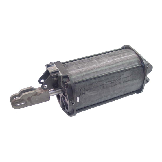
SM-1000.51
Pneuma c Cylinder
14" Bore X 20" Stroke
Part No. R434001025
(formerly P ‐324285‐00000)
material. Also, the area in which the cylinder is to be
mounted should be free of any foreign objects, which may
damage the cylinder barrel. To further ensure a long, trouble‐
free service, an efficient air filter should be installed in the
system's supply line.
Start the installa on by removing one co er pin and clevis pin
from the clevis on the cap end of the cylinder. Set the cylinder
into the moun ng posi on with the cap clevis ma ng with the
moun ng eye. Reinstall the clevis pin through the clevis lugs,
and the co er pin into the clevis pin. Spread the ends of each
co er pin so that they will not fall out. You can now connect
the piston rod end to the moun ng bracket, no ng proper
alignment to eliminate any binding.
Remove the thread protectors from each pipe port in the head
and cap; connect air lines from the direc onal control valve.
Use pipe dope on the air line fi ngs, not any kind of tape. Be
sure no foreign ma er enters the ports or air lines during the
me they are open.
If the cylinder is to be painted, be sure that the piston rod is
covered, the ports are closed, and the clevis pin is covered
where it rides in the clevis.
The supply air and atmospheric (ambient) condi on must be
maintained within a temperature range of –40°F to +225°F.
Advertisement

Subscribe to Our Youtube Channel
Related Manuals for Aventics R434001025


Summary of Contents for Aventics R434001025
- Page 1 Pneuma c Cylinder 14” Bore X 20” Stroke Part No. R434001025 (formerly P ‐324285‐00000) WARNING: INSTALLATION material. Also, the area in which the cylinder is to be AND MOUNTING mounted should be free of any foreign objects, which may damage the cylinder barrel. To further ensure a long, trouble‐...
- Page 2 General Maintenance Recommendations OPERATION REASSEMBLY – Use the exploded view as a guide and When the cylinder installa on is completed correctly, air lubricate all seals and grooves with Shell Oil Company’s pressure delivered from the direc onal valve to the port on Aeroshell Grease 14.
- Page 3 Parts List - Cylinder Complete Part No. R434001025 Ref. No. Description Qty. Pc. No. R434001251 Tube R434001073 Head Assembly R434001258 (includes items 3 to 7) Head Latch Stud 1/8" Shim Kit: Piston, Tube & Rod Seal R434001001 (includes items 8 to 12)
-
Page 4: Product Changes
No charge will be made for labor with respect to defects covered by this Warranty, provided that the work is done by AVENTICS or any of its authorized service facilities. - Page 5 SM-1000..51/May 2014 Subject to change. Printed in United States. AVENTICS Corporation. This document, as well as the data, specifications, and other information set forth in it, are the exclusive property of AVENTICS. It may not be reproduced or given to third parties without its consent.
Need help?
Do you have a question about the R434001025 and is the answer not in the manual?
Questions and answers