Advertisement
Quick Links
40
1
2
3 4
41
39
33
38
37
35 34
36
32
45
44
43
42
31
30
29
46
47
28
27
26
23
25
24
ATX Power
13
No.
Pin Define
No.
Pin Define
1
3.3V
13
3.3V
2
3.3V
14
-12V
3
GND
15
GND
4
+5V
16
PS_ON
5
GND
17
GND
6
+5V
18
GND
7
GND
19
GND
8
Power Good
20
-5V
9
5VSB
21
+5V
10
+12V
22
+5V
12
11
+12V
23
+5V
24
12
3.3V
24
GND
SATA Connector/SATA DOM
No.
Pin Define
3
1
GND
9
2
TXP
3
1
1
3
TXN
2
4
GND
1
5
RXN
No.
Pin Define
6
RXP
1
5V
7
GND
1
2
GND
8
5V
9
GND
3
No Connect
USB 3.0 Header
No.
Pin Define
No.
Pin Define
1
Power
11
IntA_P2_D+
20
1
2
IntA_P1_SSRX-
12
IntA_P2_D-
3
IntA_P1_SSRX+
13
GND
4
GND
14
IntA_P2_SSTX+
5
IntA_P1_SSTX-
15
IntA_P2_SSTX-
6
IntA_P1_SSTX+
16
GND
11
10
7
GND
17
IntA_P2_SSRX+
8
IntA_P1_D-
18
IntA_P2_SSRX-
9
IntA_P1_D+
19
Power
10
NC
20
No Pin
Jumper Settings
No.
1
1
J1
J2
Rear I/O Connector
1
4
5
7
3
8
9
2
6
No.
Desription
1
Server Management LAN port
2
USB 3.0 ports
3
VGA port
4
GbE Ethernet LAN port #2
5
GbE Ethernet LAN port #1
6
ID button with LED
7
SFP+ LAN#2 link/Active LED
8
SFP+ LAN port #2
9
SFP+ LAN port #1
10
SFP+ LAN#1 link/Active LED
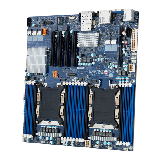
MD61-SC2 Quick Reference Guide
5
6
12
No.
Code
1
LED_LAN1
2
SFP+_1_2
7
3
LED_LAN2
4
SW_ID
13
5
LAN1_2
14
11
6
VGA
15
7
COM1
8
9
8
U2_0
9
U2_1
10
MEZZ_2
16
10
11
MEZZ_1
17
12
USB3_MLAN
18
13
BAT
14
PMBUS
19
15
ATX1
16
SYS_FAN5
17
CPU1_FAN1
18
CPU0_FAN1
19
P12V_AUX2
20
SYS_FAN4
21
SYS_FAN3
22
SYS_FAN2
23
P12V_AUX1
24
SYS_FAN1
CPU1
25
SW_RAID
(Secondary)
26
LAN4_AC1
27
LAN3_AC1
28
FP_1
29
J2
30
J1
31
CLR_CMOS
32
33
F_USB3
34
SL_CN1
35
SL_CN2
36
SL_CN3
22
21
20
CPU/System FAN
4 8
5 1
No.
1
4
1
2
3
4
1
1 5
8 4
4
No.
Pin Define
1
GND
PMBUS
2
GND
3
GND
No.
Pin Define
5
4
GND
1
PMBus Clock
5
+12V
2
PMBus Data
6
+12V
3
PMBus Alert
7
+12V
4
GND
8
+12V
1
5
3.3V Sense
TPM Connector
No.
Pin Define
No.
Pin Define
1
Clock
8
No Connect
2
P_3V3_AUX
9
No Connect
13
14
3
SPI_RST
10
No Pin
4
P3V3
11
No Connect
5
SPI_MISO
12
GND
6
IRQ_SERIAL
13
SPI_CS
7
SPI_MOSI
14
GND
COM2 Connector
IPMB
No.
Pin Define
1
NDCD-
10 9
1
2
NSIN
3
NSOUT
No.
Pin Define
4
NDTR-
1
Clock
5
GND
2
GND
6
NDSR-
2 1
3
Data
7
NRTS-
4
VCC
8
NCTS-
9
NRI-
10
No Pin
Desription
Clear CMOS Jumper
1-2 Close: Normal operation (Default setting)
2-3 Close: Clear CMOS data.
ON
OFF
1
HOST_SMBUS_SEL
BIOS defined
2
PMBUS_SEL
BIOS defined
3
S3_MASK
BIOS defined
4
DB_PLD
CPLD debug mode
Normal [Default]
ON
OFF
ME_UPDATE
Force ME update
1
Normal [Default]
BIOS_PWD
2
Clear supervisor password
Normal [Default]
3
BIOS_RCVR
BIOS recovery mode
Normal [Default]
4
ME_RCVR
ME recovery mode
Normal [Default]
10/100/1000 LAN LED:
Speed LED Link/Activity
LED
State
Description
Yellow On
1Gbps data rate
10
Green On
100Mbps data rate
Off
10Mbps data rate
Green LED
SFP+ LAN LED:
State
Description
Yellow On
1 Gbps data rate
Yellow LED
Green On
10 Gbps data rate
ID button/LED:
State
Description
System identifcation
Blue On
is active.
System identifcation
Off
is disabled.
Description
SFP+ LAN port#1 Active LED
SFP+ LAN port #1 (Left)
SFP+ LAN port #2 (Right)
SFP+ LAN#2 link/Active LED
ID button with LED
GbE LAN port #1 (Left)
GbE LAN port #2 (Right)
VGA port
Serial port cable connector
Slimline connector #1 (PCIe x4 signal)
Slimline connector #2(PCIe x4 signal)
PCIe x 8 slot (Proprietary/for mezzanine card)
PCIe x 8 slot (Proprietary/for mezzanine card)
Sever management LAN port (top)/USB 3.0 ports (buttom)
Battery socket
PMBus connector
2x12 pin main power connector
System fan connector#5
CPU fan connector (for secondary CPU)
CPU fan connector (for primary CPU)
2x4 pin 12V power connector (for secondary CPU)
System fan connector#4
System fan connector#3
System fan connector#2
2x4 pin 12V power connector (for primary CPU)
System fan connector#1
VROC key
LAN#4 Active LED
LAN#3 Active LED
Front panel header
Function jumper switch #2
Function jumper switch #1
Clear CMOS jumper
Error LED for DIMM slots
USB 3.0 header
Slimline connector #1 (SATA 6Gb/s signal/for SATA#0~#3)
Slimline connector #2 (SATA 6Gb/s signal/for SATA#4~#7)
Slimline connector #3 (SATA 6Gb/s signal/for sSATA#0~#3)
Pin Define
GND
+12V
Sense
Speed Control
1
DIMM
4
Capacity
Ranks Per
(GB)
Type
DIMM and
Data Width
DIMM Density
4Gb
8Gb
8Gb
RDIMM
SRx4
4GB
8GB
16GB
8GB
16GB
32GB
RDIMM
SRx8
RDIMM
DRx8
8GB
16GB
32GB
RDIMM
DRx4
16GB
32GB
64GB
N/A
QRx 4
2H-64GB
2H-128GB
RDIMM
8Rx 4
3DS
N/A
4H-128GB
4H-256GB
LRDIMM
QRx4
32GB
64GB
128GB
QRx4
N/A
2H-64GB
2H -128GB
LRDIMM
3DS
8Rx4
N/A 4H- 128GB
4H-256GB
NOTE!
1. 2933MHz for 2nd Generation Intel® Xeon® Scalable Processors only
2. Intel® Optane™ DC Persistent Memory for 2nd Generation Intel® Xeon®
Scalable Processors only
Channel2
Modes
Slot1
AD
--
MM
--
AD+MM
--
Channel2
Modes
Slot1
AD
--
AD*
--
* 2nd socket has no DCPMM DIMM
AD=All Modes; MM= Memory Mode.
For MM, general NM/FM ratio is between 1:4 and 1:16. Excess capacity for FM can be used for AD (NM= Near Memory; FM= Far Memory)
For each individual population, sockets are normally symmetric with exceptions for 1DCPMM per socket and 1 DCPMM per node case.
DRAM1
DRAM2
DRAM3
DCPMM
No DDR4 single rank x8 for either DCPMM Memory Mode or APP-Direct Mode
No mixing of DCPMM and NVDIMMs within the platform.
DDR channel and DIMM slot nomenclature may vary depending on platform implementation.
Matrix targets configs for optimized Intel Optane DCPMM to DRAM cache ratio in MM and MM + AD modes.
No.
Code
Description
37
SSATA5
SATA 6Gb/s connector #5
38
SATA_DOM1
SATA DOM support power connector for SSATA port #5
39
TPM
TPM connector
40
LED_BMC
BMC firmware readiness LED
41
IPMB
IPMB connector
42
PCIE_4
PCIe x16 slot #4 (Gen3 x16)
43
PCIE_3
PCIe x16 slot #3 (Gen3 x16)
44
PCIE_2
PCIe x16 slot #2 (Gen3 x16)
45
PCIE_1
PCIe x16 slot #1 (Gen3 x16)
46
SSATA4
SATA 6Gb/s connector #4
47
SATA_DOM0
SATA DOM support power connector for SSATA port #4
Front Panel Header #1
No.
Pin Define
No.
Pin Define
1
Power LED+
2
5V Standby
1
2
4
ID LED+
3
No Pin
6
ID LED-
5
Power LED-
8
System Status LED+
7
HDD LED+
10
System Status LED-
9
HDD LED-
12
LAN1 Active LED+
11
Power Button
14
LAN1 Link LED-
13
GND
16
SMBus Data
15
Reset Button
18
SMBus Clock
17
GND
20
Case Open
19
ID Button
23
24
22
LAN2 Active LED+
21
GND
24
LAN2 Link LED-
23
NMI Switch
Installing CPU and Heat Sink
3
2
Memory Population Configuration
Speed (MT/s); Voltage (V)
Slot Per Channel (SPC)
DIMM Per Channel (DPC)
1 Slot per
2 Slot per Channel
Channel
1DPC
1DPC
2DPC
1.2V
1.2V
1.2V
2933
2933
2666
Intel Optane DCPMM DIMM Population Rule
Symmetric Population with the Socket
iMC0
iMC1
Channel1
Channel0
Channel2
Channel1
Slot0
Slot1
Slot0
Slot1
Slot0
Slot1
Slot0
Slot1
DRAM1
--
DRAM1
DCPMM
DRAM1
--
DRAM1
--
DRAM2
DRAM2
DRAM2
--
DCPMM
--
DRAM2
--
DRAM3
--
DRAM3
DCPMM
DRAM3
--
DRAM3
--
Asymmetric Population with the Socket
iMC0
iMC1
Channel1
Channel0
Channel2
Channel1
Slot0
Slot1
Slot0
Slot1
Slot0
Slot1
Slot0
Slot1
DRAM1
--
DRAM1
--
DRAM1
--
DRAM1
--
DRAM1
--
DRAM1
--
DRAM1
DRAM1
--
--
DDR4 Type
RDIMM
3DS RDIMM
LRDIMM
3DS LRDIMM
RDIMM
--
--
--
RDIMM
3DS RDIMM
LRDIMM
--
Capacity
Any Capacity (uniformly for all channels for a given configuration
BMC Firmware Readiness LED
BMC Firmware Readiness LED (LED_BMC1):
State
Description
On
BMC firmware is initial
Blink
BMC firmware is ready
Off
AC loss
3
1
2
4
4
DIMM Status LED:
State
Description
Description
Off
Normal operation
Red On
Error/DIMM
missing
Channel0
Slot0
Slot1
Slot0
DRAM1
DCPMM
DRAM1
2-1-1
DRAM2
DRAM2
DCPMM
2-1-1
DRAM3
DCPMM
DRAM3
2-1-1
Channel0
Slot0
Slot1
Slot0
DRAM1
DCPMM
DRAM1
2/1-1-1
DRAM1
DRAM1
DCPMM
2/1-1-1
Capacity
See Validation Matrix
(DDR4 DIMMs Vaildated
with DCPMM*)
Advertisement

Related Manuals for Gigabyte MD61-SC2


Summary of Contents for Gigabyte MD61-SC2
- Page 1 MD61-SC2 Quick Reference Guide Code Description Code Description LED_LAN1 SFP+ LAN port#1 Active LED SSATA5 SATA 6Gb/s connector #5 SFP+_1_2 SFP+ LAN port #1 (Left) SATA_DOM1 SATA DOM support power connector for SSATA port #5 SFP+ LAN port #2 (Right)
- Page 2 Restriction of Hazardous Substances (RoHS) Directive Statement Email: server.grp@gigabyte.com GIGABYTE products have not intended to add and safe from hazardous substances (Cd, Pb, Hg, Cr+6, PBDE and PBB). The parts and components Facebook: https://www.facebook.com/gigabyteserver have been carefully selected to meet RoHS requirement. Moreover, we at GIGABYTE are continuing our efforts to develop products that do not use internationally banned toxic chemicals.
Need help?
Do you have a question about the MD61-SC2 and is the answer not in the manual?
Questions and answers