Advertisement
Quick Links
1
2
3 4
5
6
7
8
9
37
36
35
34
33
32
31
30
29
28
Back Light Switch Header
Front Panel Header/ 前面板
No.
1
2
1
2
1
No.
Pin Define
2
1
Back light down
3
2
Back light up
4
5
9
10
SATA Connector/SATA 接口
6
7
8
No.
Pin Define
7
9
1
GND
10
2
TXP
3
TXN
Battery Cable Connector
4
GND
5
RXN
1
6
RXP
2
7
GND
No.
Pin Define
1
Battery+
2
GND
Hard disk power connectornnector
N2
No.
Pin Define
No.
Pin Define
1
VCC3
11
GND
2
VCC3
12
GND
No.
3
VCC3
13
+12V
1
40
1
4
GND
14
+12V
2
5
GND
15
+12V
3
6
GND
P1
GND
4
7
VCC
P2
GND
5
8
VCC
N1
GND
6
1
9
VCC
N2
GND
7
10
GND
8
9
10
NOTE! Cable detect pin 24 must connect to ground.
Speaker Cable Connector
Monitor Power Switch
No.
Pin Define
1
4
1
Speaker Out R-
1
No.
Pin Define
2
Speaker Out R+
1
High/Low: turn on/off monitor
3
Speaker Out L+
2
GND
2
4
Speaker Out L-
PN:12QM1-MDH110-00R
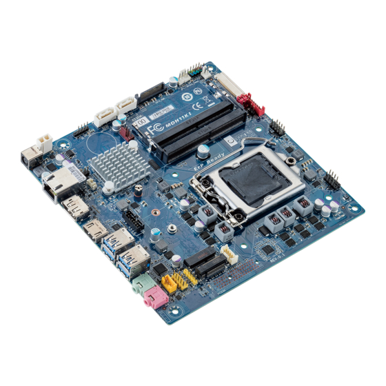
MDH11KI Quick Reference Guide/ 快速测试参考指南
No.
Code
10 11
12
13
1
FP_AUDIO
2
SPKR
3
MIC_IN
4
LINE_OUT
5
USB3_2
6
USB3_1
7
TPM_LPC
14
8
HDMI
9
DP
10
LAN
11
BATTERY
15
12
CLR_CMOS
13
DC_IN
14
ATX_19V
15
FUSB2_5
16
SATAIII_1
16
17
SATAIII_0
18
SATA_PWR
19
CPU_FAN
17
20
SYS_PANEL
22
21
MON_SW
22
SYS_FAN
23
SODIMM2
18
24
SODIMM1
24
23
25
FPD_PWR
26
LVDS
27
FPD
28
BL_SW
19
29
LCD_VCC
30
FUSB2_3
31
CPU
20
25
32
FUSB2_2
33
FUSB2_4
21
34
M2_E
35
COM1
36
M2_M
27
26
37
DMIC_CON
Pin Define
2
10
HDD LED+
1
9
Power LED+
No.
Pin Define
No.
Pin Define
HDD LED-
1
Power (5V)
6
USB DY+
Power LED-
2
Power (5V)
7
GND
GND
3
USB DX-
8
GND
Power Button+
4
USB DY-
9
No Pin
Reset Button
5
USB DX+
10
No Connect
Power Button-
No Connect
No Pin
Serial Port Cable Connector
No.
Pin Define
1
1
9
1
NDCD-
2
NDSR-
3
NRXD-
4
NRTS-
2
10
5
NTXD-
LVDS
Pin Define
No.
Pin Define
No.
Pin Define
No.
+RXO3_C
11
+RXE2_C
21
No Connect
31
-RXO3_C
12
-RXE2_C
22
VCC3
32
+RXO2_C
13
+RXE1_C
23
GND
33
-RXO2_C
14
-RXE1_C
24
-Cable Detect
34
+RXO1_C
15
+RXE0_C
25
GND
35
-RXO1_C
16
-RXE0_C
26
+RXECLKO_C
36
+RXO0_C
17
GND
27
-RXECLKO_C
37
-RXO0_C
18
LCD_VCC
28
GND
38
+RXE3_C
19
LCD_VCC
29
GND
39
-RXE3_C
20
LCD_VCC
30
GND
40
Digital MIC In Connector
1
5
No.
Pin Define
1
VCC
2
DMIC DATA
3
GND
4
DMIC CLK
5
No Pin
Description
Front audio header
Speaker cable connector
Audio Mic In port
Audio Line Out port
USB 3.0 ports
USB 3.0 ports
TPM connector
HDMI 2.0 port
Display port connector
GbE LAN port
Battery cable connector
Clear CMOS jumper
DC In power connector
2 pin power connector
USB 2.0 header
SATA 6Gb/s connector
SATA 6Gb/s connector
Hard disk power connector
CPU fan connector
Front panel header
Monitor power switch header
System fan connector
DDR4 SO-DIMM slot#2
DDR4 SO-DIMM slot#1
LVDS power select jumper (12V/19V)
LVDS connector
Flat Panel Display connector
Back light brightness switch
LVDS Drive voltage jumper
USB 2.0 header
Intel LGA1151 socket
USB 2.0 header
USB 2.0 header
M.2 slot (PCIe Gen2 x1, Support NGFF-2230, E-Key)
Serial port header
M.2 slot (PCIe Gen2 x4 or SATA 6Gb/s
Support NGFF-2260/2280, M-Key)
Digital Mic connector
USB 2.0 Header
5
1
No.
Pin Define
5
1
VCC
2
USB-
3
USB+
4
GND
1
5
No Pin
Flat Panel Display Connector
No.
Pin Define
6
NCTS-
8
1
7
NDTR-
8
5V
9
GND
10
No Connect
No.
Pin Define
1
Backlight enable
2
Backlight control
3
Backlight inverter power
4
Backlight inverter power
Pin Define
5
GND
SMB_CLK_CON
6
GND
SC_BKLT_EN
7
Panel brightness increase
SC_BKLT_CTRL
8
Panel brightness decrease
+RXECLKE_C
-RXECLKE_C
FPD_19V
FPD_19V
FPD_19V
No Connect
SMB_DATA_CON
Front Audio Connector/ 前置音频
No.
Pin Define
No.
Pin Define
9
1
1
MIC2_L
6
MIC2_JD
2
GND
7
GND
10
2
3
MC2_R
8
No Pin
4
FP_AUDIO_DET
9
LINE2_L
5
LINE2_R
10
LINE2_JD
Rear I/O Connector/ 后面板接口
1
2
3
4
5
5
No.
Desription
No.
Desription
1
DC In power connector
5
USB 3.0 ports
2
GbE Eternet LAN port
6
Line Out port (Green)
3
Display port connector
7
Mic In port (Pink)
4
HDMI 1.4 port
The HDMI connector is HDCP compliant and supports Dolby True HD and DTS HD
Master Audio formats. It also supports up to 192KHz/24bit 8-channel LPCM audio
output. You can use this port to connect your HDMI-supported monitor. The
maximum supported resolution is 4096x2160@24Hz or 2560x1600@60Hz, but the
actual resolutions supported are dependent on the monitor being used.
Power Connector/ 电源
1
No.
Pin Define
1
GND
2
19V
2
Installing CPU/ 安装 CPU
Memory Population Configuration/
Jumper Settings/ 跳线设置
1
No.
1
2
3
3
2
6
7
Speed LED Link/Activity
LED
10/100/1000 LAN LED:
State
Description
Amber On
1Gbps data rate
Green On
100Mbps data rate
Off
10Mbps data rate
CPU/System FAN/ 风扇
No.
Pin Define
4
1
GND
2
+12V
4
1
3
Sense
4
Speed Control
1
安装内存
1
2
Desription
Clear CMOS Jumper
Open: Normal operation (Default setting)
Close: Clear CMOS data.
LVDS Back Light Power Select Jumper
1-2 Close: Set to 12V.
2-3 Close: Set to 19V. (Default setting)
LVDS Logic/LCD Drive Voltage Jumper
1-2 Close: Set to 3V.
2-3 Close: Set to 5V. (Default setting)
Advertisement

Related Manuals for Gigabyte MDH11KI


Summary of Contents for Gigabyte MDH11KI
- Page 1 MDH11KI Quick Reference Guide/ 快速测试参考指南 Code Description 10 11 Rear I/O Connector/ 后面板接口 FP_AUDIO Front audio header SPKR Speaker cable connector MIC_IN Audio Mic In port LINE_OUT Audio Line Out port USB3_2 USB 3.0 ports USB3_1 USB 3.0 ports Speed LED Link/Activity...
- Page 2 Restriction of Hazardous Substances (RoHS) Directive Statement GIGABYTE products have not intended to add and safe from hazardous substances (Cd, Pb, Hg, Cr+6, PBDE and PBB). The parts and components have been carefully selected to meet RoHS requirement. Moreover, we at GIGABYTE are continuing our efforts to develop products that do not use internationally banned toxic chemicals.
Need help?
Do you have a question about the MDH11KI and is the answer not in the manual?
Questions and answers