Table of Contents
Advertisement
Quick Links
Advertisement
Table of Contents

Related Manuals for Gigabyte MX32-4L0


Summary of Contents for Gigabyte MX32-4L0
- Page 1 MX32-4L0 Intel Socket LGA1151 processor motherboard ® User's Manual Rev. 1001...
- Page 2 GIGABYTE's prior written permission. Documentation Classifications In order to assist in the use of this product, GIGABYTE provides the following types of documentation: For detailed product information, carefully read the User's Manual.
-
Page 3: Table Of Contents
Table of Contents MX32-4L0 Motherboard Layout ..................5 Block Diagram .........................7 Chapter 1 Hardware Installation ..................8 Installation Precautions ..................8 1-2 Product Specifications ..................9 Installing the CPU and CPU Cooler ............... 11 1-3-1 Installing the CPU ....................11 1-3-2 Installing the CPU Cooler ..................13 Installing the Memory .................. - Page 4 2-3-1 Syetem Agent (SA) Configuration ................60 2-3-2 PCH-IO Configuration ....................61 Server Management Menu ................62 2-4-1 System Event Log ....................64 2-4-2 View FRU Information ....................65 2-4-3 BMC Network Configuration ...................66 2-4-4 IPv6 BMC Network Configuration ................67 Security Menu ....................68 2-5-1 Secure Boot ......................69 Boot Menu ...................... 71 2-6-1 UEFI NETWORK Drive BBS Priorities ..............73 ..............
-
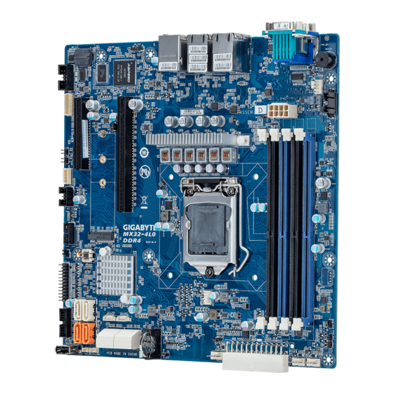
Page 5: Mx32-4L0 Motherboard Layout
MX32-4L0 Motherboard Layout 14 13 - 5 -... - Page 6 Item Code Description SW_ID ID button with LED USB3_MLAN Server management LAN port (top)/ USB3.0 ports (bottom) LAN1_2 GbE Ethernet LAN port #1 (top) / #2 (bottom) LAN3_4 GbE Ethernet LAN port #3 (top) / #4 (bottom) 8 pin power connector (for CPU, DDR) COM1_VGA Serial port (top)/VGA port (bottom) PMBUS...
-
Page 7: Block Diagram
Block Diagram - 7 -... -
Page 8: Chapter 1 Hardware Installation
Chapter 1 Hardware Installation Installation Precautions The motherboard contains numerous delicate electronic circuits and components which can become damaged as a result of electrostatic discharge (ESD). Prior to installation, carefully read the user's manual and follow these procedures: • Prior to installation, do not remove or break motherboard S/N (Serial Number) sticker or warranty sticker provided by your dealer. -
Page 9: Product Specifications
1-2 Product Specifications Supports Intel® Xeon® E-2100 Processors Š 8th Gen. Intel Core™ i3/ Pentium®/ Celeron® Processors Š Chipset Intel® C246 Express Chipset Š Memory 4 x DIMM slots Š Dual channel memory architecture Š Supports 1.2V DDR4 memory Š ECC UDIMM modules supported; Up to 64GB Š... - Page 10 AMI MegaRAC SP-X Solution Web interface Š microATX Š Form Factor 244mm W x 244mm D Š GIGABYTE reserves the right to make any changes to the product specifications and product-related information without prior notice. Hardware Installation - 10 -...
-
Page 11: Installing The Cpu And Cpu Cooler
Installing the CPU and CPU Cooler Read the following guidelines before you begin to install the CPU: • Make sure that the motherboard supports the CPU. • Always turn off the computer and unplug the power cord from the power outlet before installing the CPU to prevent hardware damage. - Page 12 B. Follow the steps below to correctly install the CPU into the motherboard CPU socket. Before installing the CPU, make sure to turn off the computer and unplug the power cord from the power outlet power plug to prevent any damage to prevent damage to the CPU. Step 1: Step 2: Gently press the CPU socket lever handle down...
-
Page 13: Installing The Cpu Cooler
1-3-2 Installing the CPU Cooler Follow the steps below to correctly install the CPU cooler on the motherboard. (The following procedure uses Intel boxed cooler as the example cooler.) ® Male Push Direction of the Arrow Sign on The Top the Male Push of Female Push Pin... -
Page 14: Installing The Memory
Installing the Memory Read the following guidelines before you begin to install the memory: • Make sure that the motherboard supports the memory. It is recommended to use memory of the same capacity, brand, speed, and chips. • Always turn off the computer and unplug the power cord from the power outlet before installing the memory to prevent hardware damage. -
Page 15: Installing The M.2 Ssd Module
Installing the M.2 SSD Module Follow the steps below to install a M.2 SSD module on your motherboard. Step1. Insert the M.2 SSD module into the slot. Step2. Secure it with the screw, tightening as necessary to fasten the M.2 SSD module in place. - 15 - Hardware Installation... -
Page 16: Back Panel Connectors
Back Panel Connectors Serial Port Connects to serial-based mouse or data processing devices. VGA Port The video-in port allows connection via video in, which can also apply to the video loop thru function. RJ-45 LAN Port #3 The Gigabit Ethernet LAN port provides Internet connection at up to 1 Gbps data rate. See the section below for a description of the states of the LAN port LEDs. -
Page 17: Internal Connectors
Internal Connectors 13) PMBus ATX_12V 14) F_USB3 SATA0/ SATA1/ SATA2/ SATA3 15) F_USB2 SATA4/ SATA5 (Support SATA DOM Power) 16) COM2 SATA6/ SATA7 17) BP_1 SATA_DOM1/ SATA_DOM2 18) IPMB SATA_SGP1/ SATA_SGP2 19) TPM CPU_FAN 20) FP_1 SYS_FAN1 21) LAN3_ACT/ LAN4_ACT 10) SYS_FAN3 22) BAT 11) SYS_FAN2... - Page 18 1/2) ATX/ATX_12V (2x12 Main Power Connector and 2x4 12V Power Connector) With the use of the power connector, the power supply can supply enough stable power to all the components on the motherboard. Before connecting the power connector, first make sure the power supply is turned off and all devices are properly installed. The power connector possesses a foolproof design. Connect the power supply cable to the power connector in the correct orientation.
- Page 19 3/4/5) SATA0/SATA1/SATA2/SATA3/SATA4/SATA5/SATA6/SATA7(SATA 6Gb/s Connectors) The SATA connectors conform to SATA 6Gb/s standard and are compatible with SATA 3Gb/s standard. Each SATA connector supports a single SATA device. SATAIII_2 SATAIII_0 SATAIII_3 SATAIII_1 SATAIII_7 SATAIII_6 Pin No. Definition SATAIII_7 SATAIII_6 SATAIII_5 SATAIII_4 SATAIII_2 SATAIII_0 SATAIII_3 SATAIII_1...
- Page 20 7) SATA_SGP1/ SATA_SGP2 (SATA SGPIO) Connector Serial General Purpose Input/Output (SGPIO) is a communication method used between a host bus adapter (HBA) and a main board. Pin No. Definition Data Load Clock SATA_SGP2 SATA_SGP1 8/9/10/11/12) CPU_FAN/SYS_FAN1/SYS_FAN3/SYS_FAN2/SYS_FAN4 (CPU Fan/System Fan Headers) The motherboard has one 4-pin CPU fan header (CPU_FAN), and two 4-pin (SYS_FAN) system fan headers. Most fan headers possess a foolproof insertion design.
- Page 21 13) PMBus Connector The Power Management Bus (PMBus) is a variant of the System Management Bus (SMBus) which is targeted at digital management of power supplies. PMBus Pin No. Definition PMBus Clock PMBus Data PMBus Alert 3.3V Sense 14/15) F_USB3/ F_USB2 (USB 3.0/ 2.0 Headers) The headers conform to USB 2.0/ 3.0 specification. Each USB header can provide two USB ports via an optional USB bracket.
- Page 22 16) COM2 (Serial Port Cable Connector) The COM header can provide one serial port via an optional COM port cable. For purchasing the optional COM port cable, please contact the local dealer. COM2 Pin No. Definition NDCDB_N NSINB NSOUTB NDTRN NDSRB_N NRTSB_N NCTSB_N NRIB_N...
- Page 23 18) IPMB (Intelligent Platform Management Bus) Connector The Intelligent Platform Management Bus Communications Protocol defines a byte-level transport for transferring Intelligent Platform Management Interface Specification (IPMI) messages between intelligent I2C devices. Pin No. Definition Clock Data IPMB 19) TPM (Trusted Platform Module Connector) Trusted Platform Module (TPM) is an international standard for a secure cryptoprocessor, a dedicated microcontroller designed to secure hardware through integrated cryptographic keys.
- Page 24 20) FP_1 (Front Panel Header) Connect the power switch, reset switch, speaker, chassis intrusion switch/sensor and system status indicator on the chassis to this header according to the pin assignments below. Note the positive and negative pins before connecting the cables. Pin No.
- Page 25 22) BAT (Battery Scoket) The battery provides power to keep the values (such as BIOS configurations, date, and time information) in the CMOS when the computer is turned off. Replace the battery when the battery voltage drops to a low level, or the CMOS values may not be accurate or may be lost. • Always turn off your computer and unplug the power cord before replacing the battery. •...
-
Page 26: Jumper Settings
Jumper Settings ME Force Update Default Enable ME_UPDATE ME Recovery BIOS Recovery Default Default Enable Enable ME_RCVR BIOS_RCVR Chassis Open Intrusion Alert Case open Password Clear Clear CMOS Default Default CASE_OPEN Enable Enable BIOS_PWD CLR_CMOS Jumper Name Jumper Setting 1-2: Nomal operation (Default) ME Force Update 2-3: Enable ME Force Update 1-2: Nomal operation (Default) -
Page 27: Chapter 2 Bios Setup
Chapter 2 BIOS Setup BIOS (Basic Input and Output System) records hardware parameters of the system in the EFI on the motherboard. Its major functions include conducting the Power-On Self-Test (POST) during system startup, saving system parameters, loading the operating system etc. The BIOS includes a BIOS Setup program that allows the user to modify basic system configuration settings or to activate certain system features. When the power is turned off, the battery on the motherboard supplies the necessary power to the CMOS to keep the configuration values in the CMOS. - Page 28 Main This setup page includes all the items of the standard compatible BIOS. Advanced This setup page includes all the items of AMI BIOS special enhanced features. (ex: Auto detect fan and temperature status, automatically configure hard disk parameters.) Chipset This setup page includes all the submenu options for configuring the functions of the Platform Controller Hub. Server Management Server additional features enabled/disabled setup menus. ...
-
Page 29: The Main Menu
The Main Menu Once you enter the BIOS Setup program, the Main Menu (as shown below) appears on the screen. Use arrow keys to move among the items and press <Enter> to accept or enter other sub-menu. Main Menu Help The on-screen description of a highlighted setup option is displayed on the bottom line of the Main Menu. - Page 30 Parameter Description BIOS Information Core Version Displays the Core version information Project Name Displays the project name information. Project Version Displays version number of the BIOS setup utility. Build Date and Time Displays the date and time when the BIOS setup utility was created. Access Level Displays the access level information.
- Page 31 Parameter Description PCH Information PCH SKU / Stepping Displays the information for the installed Platform Controller Hub. Onboard LAN Information LAN1 MAC Address (Note) Displays LAN MAC address information. LAN2 MAC Address (Note) Displays LAN MAC address information. LAN3 MAC Address Displays LAN MAC address information.
-
Page 32: Advanced Menu
Advanced Menu The Advanced Menu displays submenu options for configuring the function of various hardware components. Select a submenu item, then press <Enter> to access the related submenu screen. BIOS Setup - 32 -... -
Page 33: Cpu Configuration
2-2-1 CPU Configuration Parameter Description CPU Configuration Type / ID / Speed / L1 Data Cache / L1 Instruction Cache / L2 Cache/ L3 Displays the technical specifications for the installed processor Cache Enable/Disable CPU Hardware Prefetcher. Hardware Prefetcher Options available: Enabled/Disabled. Default setting is Enabled. Enable/Disable Adjacent Cache Line Prefetch. Adjacent Cache Line Prefetch Options available: Enabled/Disabled. Default setting is Enabled. Enable/Disable VT-x function. -
Page 34: Pci Subsystem Settings
2-2-2 PCI Subsystem Settings Parameter Description PCI Bus Driver Version Displays the PCI Bus Driver version information. When enabled, this setting will initialize the device expansion PCI Express Slot #1 / #2 I/O ROM ROM for the related PCI-E slot. (Note1) Options available: Enabled/Disabled. -
Page 35: Power & Performance Settings
2-2-3 Power & Performance Settings Parameter Description Power & Performance CPU-Power Management Control Press [Enter] to configure advanced items. - 35 - BIOS Setup... - Page 36 Parameter Description CPU-Power Management Control Select the performance state that the BIOS will set starting from reset vector. Boot performance mode Options available: Max Non-Turbo Performance, Turbo Performance. Default setting is Turbo Peroformance. Conventional Intel SpeedStep Technology switches both voltage and frequency in tandem between high and low levels in Intel(R) SpeedStep(tm) response to processor load.
- Page 37 Parameter Description Press [Enter] to configure advanced items. Energy Efficient P-state Š – Enable/Disable Energy Efficient P-state feature. – Options available: Enabled/Disabled. Default setting is View / Configure Turbo Options Enabled. • Energy Efficient Turbo – Enable/Disable Energy Efficient Turbo feature. – Options available: Enabled/Disabled. Default setting is Enabled. Enable/Disable CPU power states. C states Options available: Enabled/Disabled. Default setting is Enabled. Configures the limit on the C-State package register.
-
Page 38: Server Me Configuration
2-2-4 Server ME Configuration Parameter Description Server ME Configuration ME Firmware Status #1/#2 Displays ME Firmware status information. Current State (for ME Firmware) Displays ME Firmware current status information. Error Code (for ME Firmware) Displays ME Firmware status error code. BIOS Setup - 38 -... -
Page 39: Trusted Computing
2-2-5 Trusted Computing Parameter Description Configuration Enable/Disable the TPM support feature. Security Device Support Options available: Enable/Disable. Default setting is Enable. Current Status Information Displays current TPM status information. - 39 - BIOS Setup... -
Page 40: Serial Port Console Redirection
2-2-6 Serial Port Console Redirection Parameter Description Select whether to enable console redirection for specified device. Console COM1/COM2 Serial Over redirection enables the users to manage the system from a remote LAN Console Redirection (Note) location. Options available: Enabled/Disabled. Default setting is Disabled. Selects a COM port for legacy serial redirection. The options are Legacy Console Redirection dependent on the available COM ports. - Page 41 Parameter Description Bits per second Š – Selects the transfer rate for console redirection. – Options available: 9600, 19200, 38400, 57600, 115200. Default setting is 115200. Data Bits Š – Selects the number of data bits used for console redirection. –...
- Page 42 Parameter Description Redirection After BIOS POST (Note) Š – This item allows user to enable console redirection after OS has loaded. COM1/COM2 Serial LAN/ – Options available: Always Enable/Boot Loader. Default setting is Legacy/Serial Port for Out- Always Enable. of-Band EMS Console Out-of-Band Mgmt Port Š...
-
Page 43: Ast2500 Super Io Configuration
2-2-7 AST2500 Super IO Configuration Parameter Description AST2500 Super IO Configuration Super IO Chip Displays the Super IO Chip information. Serial Port 1/2 Configuration Press [Enter] to configure advanced items. - 43 - BIOS Setup... - Page 44 Parameter Description Serial Port Š – When set to Enabled allows you to configure the serial port settings. When set to Disabled, displays no configuration for the serial port. – Options available: Enabled/Disabled. Default setting is Enabled. Device Settings Š – Displays the serial port base I/O address and IRQ. Change Settings: Š...
-
Page 45: Network Stack Configuration
2-2-8 Network Stack Configuration Parameter Description Enable/Disable the UEFI network stack. Network Stack Options available: Enabled/Disabled. Default setting is Enabled. Enable/Disable the Ipv4 PXE feature. Ipv4 PXE Support (Note) Options available: Enabled/Disabled. Default setting is Enabled. Enable/Disable the Ipv4 HTTP feature. Ipv4 HTTP Support (Note) Options available: Enabled/Disabled. -
Page 46: Usb Configuration
2-2-9 USB Configuration Parameter Description USB Configuration USB Devices: Displays the USB devices connected to the system. Enable/Disable the XHCI (USB 3.0) Hand-off support. XHCI Hand-off Options available: Enabled/Disabled. Default setting is Enabled. USB hardware delays and time-outs Select the time-out value for USB Control/Bulk?Interrupt transfers. USB transfer time-out Options available: 1 sec, 5 sec, 10 sec and 20sec. -
Page 47: Runtime Error Logging Settings
2-2-10 Runtime Error Logging Settings Parameter Description Runtime Error Logging Settings Runtime Error Logging System Enable/Disable runtime logging error system function. Enabling Options available: Enable/Disabled. Default setting is Enable. Enable/Disable the Memory Error log function Memory Error Enabling Options available: Enable/Disabled. Default setting is Enable. Enable/Disable the PCI/PCI log function PCI/PCI Error Enabling Options available: Enable/Disabled. -
Page 48: S5 Rtc Wake Settings
2-2-11 S5 RTC Wake Settings Parameter Description Enable/Disable system wake on alarm event. Options available: Disabled/Fixed Time. When Fixed Time enabled, system Wake System from S5 will wake on the hr::min::sec specified. Default setting is Enable. BIOS Setup - 48 -... -
Page 49: Nvme Configuration
2-2-12 NVMe Configuration Parameter Description NVMe Configuration Displays the NVMe devices connected to the system - 49 - BIOS Setup... -
Page 50: Offboard Sata Controller Configuration
2-2-13 OffBoard SATA Controller Configuration Parameter Description Offboard SATA Controller Displays the information on your PCIe SATA controllers/ PCIe SSD if installed Configuration BIOS Setup - 50 -... -
Page 51: Chipset Configuration
2-2-14 Chipset Configuration Parameter Description Defines the power state to resume to after a system shutdown that is due to an interruption in AC power. When set to Last State, the system will return to the active power state prior to shutdown. When set to Restore on AC Power Loss (Note) Power Off, the system remains off after power shutdown. Options available: Last State, Power Off, Power On. -
Page 52: Iscsi Configuration
2-2-15 iSCSI Configuration Parameter Description iSCSI Initiator Name Add an Attempt Press [Enter] to configure advanced items. Delete Attempts Press [Enter] to configure advanced items. Change Attempt Order Press [Enter] to configure advanced items. BIOS Setup - 52 -... -
Page 53: Intel(R) I210 Gigabit Network Connection
2-2-16 Intel(R) I210 Gigabit Network Connection - 53 - BIOS Setup... - Page 54 BIOS Setup - 54 -...
- Page 55 Parameter Description Press [Enter] to configure advanced items. Link Speed Š – Allows for automatic link speed adjustment. – Options available: Auto Negotiated, 10 Mbps Half, 10 Mbps Full, 100 Mbps Half, 100 Mbps Full. Default setting is Auto Negotiated. NIC Configuration Wake On LAN Š – Enables power on of the system via LAN. Note that configuring Wake on LAN in the operating system does not change the value of this setting, but does override the behavior of Wake on LAN in OS controlled power states.
-
Page 56: Vlan Configuration
2-2-17 VLAN Configuration BIOS Setup - 56 -... - Page 57 Parameter Description Press [Enter] to configure advanced items. Create new VLAN Š VLAN ID Š – Sets VLAN ID for a new VLAN or an existing VLAN. – Press the <+> / <-> keys to increase or decrease the desired values. – The valid range is from 0 to 4094. Priority Š...
-
Page 58: Driver Health
2-2-18 Driver Health Parameter Description Driver Health Displays driver health status of the devices/controllers if installed BIOS Setup - 58 -... -
Page 59: Chipset Setup Menu
Chipset Setup Menu Chipset Setup menu displays submenu options for configuring the function of Platform Controller Hub(PCH). Select a submenu item, then press <Enter> to access the related submenu screen. - 59 - BIOS Setup... -
Page 60: Syetem Agent (Sa) Configuration
2-3-19 Syetem Agent (SA) Configuration Parameter Description Press [Enter] to configure advanced items. Memory Frequency Š – Displays the frequency inforamtion of installed memory. Channel and slot information of memory DIMMs. Š Maximum Memory Frequency Š – Configure the maxium memory frequency. Memory Configuration – Default setting is Auto. Max TOLUD Š – Maximum Value of TOLUD. -
Page 61: Pch-Io Configuration
2-3-20 PCH-IO Configuration Parameter Description PCH-IO Configuration Press [Enter] to configure advanced items. SATA Controller Š – Enable/Disable SATA controller. – Options available: Enabled/Disabled. Default setting is Enabled. SATA Mode Selection Š – Configures on chip SATA type. – AHCI Mode: When set to AHCI, the SATA controller enables its AHCI functionality. Then the RAID function is disabled and cannot SATA Configuration be access the RAID setup utility at boot time. -
Page 62: Server Management Menu
Server Management Menu Parameter Description Enable/Disable FRB-2 timer (POST timer). FRB-2 Timer Options available: Enabled/Disabled. Default setting is Disabled. Configure the FRB2 Timer timeout. FRB-2 Timer Options available: 3 minutes, 4 minutes, 5 minutes, 6 minutes. Default setting is 6 timeout minutes. Please note that this item is configurable when FRB-2 Timer is set to Enabled. Configure the FRB2 Timer policy. FRB-2 Timer Policy Options available: Do Nothing, Reset, Power Down. - Page 63 Parameter Description System Event Log Press [Enter] to configure advanced items. View FRU Press [Enter] to view the advanced items. Information BMC network Press [Enter] to configure advanced items. configuration IPv6 BMC Network Press [Enter] to configure advanced items. Configuration - 63 - BIOS Setup...
-
Page 64: System Event Log
2-4-21 System Event Log Parameter Description Enabling / Disabling Options Change this item to enable or disable all features of System Event SEL Components Logging during boot. Options available: Enabled/Disabled. Default setting is Enabled. Erasing Settings Choose options for erasing SEL. Erase SEL Options available: No/Yes, On next reset/Yes, On every reset. -
Page 65: View Fru Information
2-4-22 View FRU Information The FRU page is a simple display page for basic system ID information, as well as System product information. Items on this window are non-configurable. (Note) The model name will vary depends on the product you purchased - 65 - BIOS Setup... -
Page 66: Bmc Network Configuration
2-4-23 BMC Network Configuration Parameter Description BMC network configuration Lan Channel 1 Select to configure LAN channel parameters statically or dynamically (DHCP). Do nothing option will not modify any BMC network parameters Configuration Address source during BIOS phase. Options available: Unspecified, Static and DynamicBmcDhcp. Default setting is DynamicBmcDhcp. Station IP address Displays IP Address information. Displays Subnet Mask information. Subnet mask Please note that the IP address must be in three digitals, for example, 192.168.000.001. -
Page 67: Ipv6 Bmc Network Configuration
2-4-24 IPv6 BMC Network Configuration Parameter Description IPv6 BMC Network Configuration IPv6 BMC Lan Channel 1 Enable/Disable IPv6 BMC LAN channel function. When this item is disabled, the system will not modify any BMC network during BIOS IPv6 BMC Lan Option phase. Options available: Unspecified, Enable and Disable. Default setting is Enable. -
Page 68: Security Menu
Security Menu The Security menu allows you to safeguard and protect the system from unauthorized use by setting up access passwords. There are two types of passwords that you can set: • Administrator Password Entering this password will allow the user to access and change all settings in the Setup Utility. •... -
Page 69: Secure Boot
2-5-25 Secure Boot The Secure Boot submenu is applicable when your device is installed the Windows 8 (or above) operating ® system. Parameter Description System Mode Displays if the system is in User mode or Setup mode. Enable/ Disable the Secure Boot function. Secure Boot Options avaiable:Enabled/Disabled. - Page 70 Parameter Description Press [Enter] to configure advanced items. Please note that this item is configurable when Secure Boot Mode is set to Custom. Factory Key Provision Š – Allows to provision factory default Secure Boot keys when system is in Setup Mode. – Options available: Enabled/Disabled. Default setting is Disabled. Restore Factory Keys Š – Installs all factory default keys. It will force the system in User Mode. –...
-
Page 71: Boot Menu
Boot Menu The Boot menu allows you to set the drive priority during system boot-up. BIOS setup will display an error message if the legacy drive(s) specified is not bootable. Parameter Description Boot Configuration Number of seconds to wait for setup activation key. 65535 (0xFFFF) Setup Prompt Timeout means indefinite waiting. Press the numeric keys to input the desired values. - Page 72 Parameter Description FIXED BOOT ORDER Priorities Press [Enter] to configure the boot priority. By default, the server searches for boot devices in the following sequence: Hard drive. Boot Option #1 / #2 / #3 / #4 / #5 CD-COM/DVD drive. USB device. Network. UEFI. UEFI Network Drive BBS Press [Enter] to configure the boot priority.
-
Page 73: Uefi Network Drive Bbs Priorities
2-6-26 UEFI NETWORK Drive BBS Priorities The UEFI network drive BBS priorities submenu allows you to specify the boot device priority from the available UEFI network drives during system boot-up. BIOS setup will display an error message if the legacy drive(s) specified is not bootable. -
Page 74: Uefi Application Boot Priorities
2-6-27 UEFI Application Boot Priorities The UEFI application boot priorities submenu allows you to specify the boot device priority from the available UEFI applications during system boot-up. BIOS setup will display an error message if the legacy drive(s) specified is not bootable. BIOS Setup - 74 -... -
Page 75: Save & Exit Menu
Save & Exit Menu The Save & Exit menu displays the various options to quit from the BIOS setup. Highlight any of the exit options then press <Enter>. Parameter Description Save Options Saves changes made and closes the BIOS setup. Save Changes and Exit Options available: Yes/No. - Page 76 Parameter Description Default Options Loads the default settings for all BIOS setup parameters. Setup Defaults are quite demanding in terms of resources consumption. If you are using low-speed memory chips or other kinds of low-performance components Restore Defaults and you choose to load these settings, the system might not function properly.
-
Page 77: Bios Post Codes
BIOS POST Codes 2-8-28 AMI Standard - PEI PEI_CORE_STARTED 0x10 PEI_CAR_CPU_INIT 0x11 PEI_CAR_NB_INIT 0x15 PEI_CAR_SB_INIT 0x19 PEI_MEMORY_SPD_READ 0x2B PEI_MEMORY_PRESENCE_DETECT 0x2C PEI_MEMORY_TIMING 0x2D PEI_MEMORY_CONFIGURING 0x2E PEI_MEMORY_INIT 0x2F PEI_MEMORY_INSTALLED 0x31 PEI_CPU_INIT 0x32 PEI_CPU_CACHE_INIT 0x33 PEI_CPU_AP_INIT 0x34 PEI_CPU_BSP_SELECT 0x35 PEI_CPU_SMM_INIT 0x36 PEI_MEM_NB_INIT 0x37 PEI_MEM_SB_INIT 0x3B PEI_DXE_IPL_STARTED... - Page 78 DXE_SB_INIT 0x70 DXE_SB_SMM_INIT 0x71 DXE_SB_DEVICES_INIT 0x72 DXE_ACPI_INIT 0x78 DXE_CSM_INIT 0x79 DXE_BDS_STARTED 0x90 DXE_BDS_CONNECT_DRIVERS 0x91 DXE_PCI_BUS_BEGIN 0x92 DXE_PCI_BUS_HPC_INIT 0x93 DXE_PCI_BUS_ENUM 0x94 DXE_PCI_BUS_REQUEST_RESOURCES 0x95 DXE_PCI_BUS_ASSIGN_RESOURCES 0x96 DXE_CON_OUT_CONNECT 0x97 DXE_CON_IN_CONNECT 0x98 DXE_SIO_INIT 0x99 DXE_USB_BEGIN 0x9A DXE_USB_RESET 0x9B DXE_USB_DETECT 0x9C DXE_USB_ENABLE 0x9D DXE_IDE_BEGIN 0xA0 DXE_IDE_RESET 0xA1 DXE_IDE_DETECT...
-
Page 79: Ami Standard - Error
2-8-30 AMI Standard - ERROR PEI_MEMORY_INVALID_TYPE 0x50 PEI_MEMORY_INVALID_SPEED 0x50 PEI_MEMORY_SPD_FAIL 0x51 PEI_MEMORY_INVALID_SIZE 0x52 PEI_MEMORY_MISMATCH 0x52 PEI_MEMORY_NOT_DETECTED 0x53 PEI_MEMORY_NONE_USEFUL 0x53 PEI_MEMORY_ERROR 0x54 PEI_MEMORY_NOT_INSTALLED 0x55 PEI_CPU_INVALID_TYPE 0x56 PEI_CPU_INVALID_SPEED 0x56 PEI_CPU_MISMATCH 0x57 PEI_CPU_SELF_TEST_FAILED 0x58 PEI_CPU_CACHE_ERROR 0x58 PEI_CPU_MICROCODE_UPDATE_FAILED 0x59 PEI_CPU_NO_MICROCODE 0x59 PEI_CPU_INTERNAL_ERROR 0x5A PEI_CPU_ERROR 0x5A PEI_RESET_NOT_AVAILABLE 0x5B... -
Page 80: Intel Upi Post Codes
2-8-31 Intel UPI POST Codes Initialize KTIRC inuput structure default values 0xA0 Collect info such as SBSP, Boot Mode, Reset type etc 0xA1 Setup IO SADs in SBSP to access the config space 0xA2 Setup up minimum path between SBSP & other sockets 0xA3 Add the node to the tree Parse the LEP of the discovered socket Check if the system has the supported topology Setup the boot path for the parent which is not... -
Page 81: Intel Mrc Post Codes
SAD setup error 0xDB RC Behavior: System Halt Unsupported topology 0xDC RC Behavior: System Halt SBSP cannot find KPIRC TXEQ Parameters for this 0xDD link in GetSocketLinkEparams(). No retry. RC Behavior: System Halt 2-8-33 Intel MRC POST Codes Detect DIMM population 0xB0 Set DDR frequency 0xB1 Gather remaining SPD data 0xB2 Program registers on the memory controller level 0xB3... -
Page 82: Intel Pm Post Codes
2-8-35 Intel PM POST Codes Start of PPM structure initialization 0xD0 PPM CSR programming 0xD1 PPM MSR programming 0xD2 Start of PState transition init 0xD3 PPM exit 0xD4 PPM On ready to boot event 0xD5 2-8-36 Intel PM POST Codes Start of IIO early Initialization 0xE0 Pre Link training... -
Page 83: Bios Post Beep Code (Ami Standard)
BIOS POST Beep code (AMI standard) 2-9-37 PEI Beep Codes # of Beeps Description Memory not Installed. Memory was installed twice (InstallPeiMemory routine in PEI Core called twice) Recovery started DXEIPL was not found DXE Core Firmware Volume was not found Recovery failed S3 Resume failed Reset PPI is not available...
Need help?
Do you have a question about the MX32-4L0 and is the answer not in the manual?
Questions and answers