Advertisement
Quick Links
1
2
43 44
45
46 47
48
42
41
40
39
(Secondary)
38
37
49
36
35
34
33
50
51
52
53
32
31
30
29
28
27
26
25
24
23
22
21
20
19
18
17
16
15
14
ATX Power
13
No.
Pin Define
No.
Pin Define
1
3.3V
13
3.3V
2
3.3V
14
-12V
3
GND
15
GND
4
+5V
16
PS_ON
5
GND
17
GND
6
+5V
18
GND
7
GND
19
GND
8
Power Good
20
-5V
9
5VSB
21
+5V
10
+12V
22
+5V
12
11
+12V
23
+5V
24
12
3.3V
24
GND
SATA Connector/SATA DOM
No.
Pin Define
3
1
GND
9
2
TXP
3
1
3
TXN
4
GND
1
5
RXN
No.
Pin Define
6
RXP
1
5V
7
GND
1
2
GND
8
5V
9
GND
3
No Connect
USB 3.0 Header
No.
Pin Define
No.
Pin Define
1
Power
11
IntA_P2_D+
20
1
2
IntA_P1_SSRX-
12
IntA_P2_D-
3
IntA_P1_SSRX+
13
GND
4
GND
14
IntA_P2_SSTX+
5
IntA_P1_SSTX-
15
IntA_P2_SSTX-
6
IntA_P1_SSTX+
16
GND
11
10
7
GND
17
IntA_P2_SSRX+
8
IntA_P1_D-
18
IntA_P2_SSRX-
9
IntA_P1_D+
19
Power
10
NC
20
No Pin
Jumper Settings
No.
1
1
Rear I/O Connector
3
5
6
1
2
4
No.
Desription
1
VGA port
2
Serial port
3
GbE Eternet LAN port #3
4
GbE Eternet LAN port #4
5
10Gb/s LAN port #2
6
10Gb/s LAN port #1
7
Server Management 10/100/1000 LAN port
8
USB 3.0 ports
9
ID button with LED
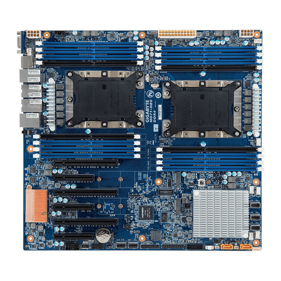
MD71-HB0 Quick Reference Guide
3
4
5 6
7
No.
Code
1
ID_SW
8
2
USB3_MLAN
9
3
LAN1
4
LAN2
5
LAN3_4
6
COM1
10
7
VGA_1
8
CPU1_FAN
9
P12V_AUX2
10
PMBUS
11
ATX1
12
P12V_AUX1
CPU1
13
SYS_FAN5
14
CPU0_FAN
15
J2
16
J1
17
SYS_FAN4
18
SYS_FAN3
19
SATA1
20
SATA0
21
SSATA0
22
SYS_FAN2
23
SYS_FAN1
24
IPMB
11
25
SATA_DOM2
26
SSATA5
27
LAN4_ACT
28
SSATA4
29
SATA_DOM1
30
SW_RAID
31
LAN3_ACT
32
F_USB3
33
FP_1
34
BMC_FLH1
35
BP_1
12
36
U2 1
37
U2 0
38
BAT
13
CPU/System FAN
5 1
4
1
No.
1
4
2
3
8 4
4
1
No.
Pin Define
1
GND
PMBUS
2
GND
3
GND
No.
Pin Define
5
4
GND
1
PMBus Clock
5
+12V
2
PMBus Data
6
+12V
3
PMBus Alert
7
+12V
4
GND
8
+12V
1
5
3.3V Sense
TPM Connector
No.
Pin Define
No.
Pin Define
1
2
1
Clock
8
No Connect
2
P_3V3_AUX
9
LPC_LAD2
3
LPC_RST
10
No Pin
4
P3V3
11
LPC_LAD3
5
LPC_LAD0
12
GND
6
IRQ_SERIAL
13
LPC_FRAME_N
13
14
7
LPC_LAD1
14
GND
IPMB
Serial Port Cable Connector
No.
Pin Define
1
NDCD-
1 2
4
2
NSIN
No.
3
NSOUT
1
4
NDTR-
2
5
GND
3
6
NDSR-
4
1
7
NRTS-
8
NCTS-
9 10
9
NRI-
10
No Pin
Desription
Clear CMOS Jumper
1-2 Close: Normal operation (Default setting)
2-3 Close: Clear CMOS data.
J1
ON
OFF
1
HOST_SMBUS_SEL
BIOS defined
2
PMBUS_SEL
BIOS defined
Stop initial power on
3
S3_MASK
Normal [Default]
when BMC is not ready
4
DB_PLD
CPLD debug mode
Normal [Default]
J2
ON
OFF
1
ME_UPDATE
Force ME update
Normal [Default]
2
BIOS_PWD
Clear supervisor password
Normal [Default]
3
BIOS_RCVR
BIOS recovery mode
Normal [Default]
4
ME_RCVR
ME recovery mode
Normal [Default]
7
Speed LED Link/Activity
LED
9
8
10/100/1000 LAN LED:
State
Description
Yellow On
1Gbps data rate
Green On
100Mbps data rate
Off
10Mbps data rate
ID button/LED:
State
Description
System identifcation
Blue On
is active.
System identifcation
Off
is disabled.
Description
ID button with LED
Sever management LAN port (top)/USB 3.0 ports
GbE Ethernet LAN port #1
GbE Ethernet LAN port #2
GbE Ethernet LAN port #3 (top)/GbE LAN port #4 (bottom)
Serial port
VGA port
CPU fan connector (for secondary CPU)
2x4 pin 12V power connector (for secondary CPU)
PMBus connector
2x12 pin main power connector
2x4 pin 12V power connector (for primary CPU)
System fan connector#5
CPU fan connector (for primary CPU)
Function jumper switch #2
Function jumper switch #1
System fan connector #4
System fan connector #3
Slimline connector #1 (SATA 6Gb/s signal/ for SATA#4~#7)
Slimline connector #0 (SATA 6Gb/s signal/ for SATA#0~#3)
Slimline connector #0 (SATA 6Gb/s signal/ for sSATA#0~#3)
System fan connector #2
System fan connector #1
IPMB connector
SATA DOM support power connector for SSATA port #5
SATA 6Gb/s connector #5
LAN#4 Active LED
SATA 6Gb/s connector #4
SATA DOM support power connector for SSATA port #4
SATA RAID upgrade key
LAN#3 Active LED
USB USB 3.0 header
Front panel header
BMC Flash ROM
HDD back plane board header
Slimline connector #1 (PCIe 3.0 x4 signal)
Slimline connector #0 (PCIe 3.0 x4 signal)
Battery socket
Pin Define
GND
+12V
Sense
Speed Control
1
2
BMC Firmware Readiness LED
BMC Firmware Readiness LED (LED_BMC):
State
Description
On
BMC firmware is initial
Blink
BMC firmware is ready
Off
AC loss
Case Open Intrusion Header
Open: Normal operation.
Closed: Active chassis intrustion alert.
LAN3/LAN4 Active LEDs
SATA RAID Upgrade Key
Pin Define
Clock
GND
2
1
No.
4
Data
1
VCC
2
No.
Pin Define
1
Enable LAN Link/Active LED
3
1
4
2
P_3V3_AUX
Channel2
Modes
Slot1
Slot0
AD
--
DRAM1
MM
--
DRAM2
AD+MM
--
DRAM3
Channel2
Modes
Slot1
Slot0
AD
--
DRAM1
AD*
--
DRAM1
* 2nd socket has no DCPMM DIMM
AD=All Modes; MM= Memory Mode.
For MM, general NM/FM ratio is between 1:4 and 1:16. Excess capacity for FM can be used for AD (NM= Near Memory; FM= Far Memory)
For each individual population, sockets are normally symmetric with exceptions for 1DCPMM per socket and 1 DCPMM per node case.
DRAM1
RDIMM
DRAM2
RDIMM
DRAM3
RDIMM
DCPMM
Any Capacity (uniformly for all channels for a given configuration
No DDR4 single rank x8 for either DCPMM Memory Mode or APP-Direct Mode
No mixing of DCPMM and NVDIMMs within the platform.
DDR channel and DIMM slot nomenclature may vary depending on platform implementation.
Matrix targets configs for optimized Intel Optane DCPMM to DRAM cache ratio in MM and MM + AD modes.
No.
Code
Description
39
CLR_CMOS
Clear CMOS jumper
40
LPC_TPM
TPM connector
41
COM2
Serial port cable connector
42
CASE_OPEN
Case open intrusion alert header
43
PCIE_1
PCIe x8 slot #1 (Gen3 x4)
44
PCIE_2
PCIe x16 slot #2 (Gen3 x16)
45
PCIE_3
PCIe x8 slot #3 (Gen3 x8)
46
PCIE_4
PCIe x16 slot #4 (Gen3 x16)
47
PCIE_5
PCIe x8 slot #5 (Gen3 x8)
48
PCIE_6
PCIe x16 slot #6 (Gen3 x16)
49
LED_BMC
BMC firmware readiness LED
50
M2_SK2
M.2 slot #2 (PCIe Gen3 x4, Support NGFF-22110/2280)
51
M2_SK1
M.2 slot #1 (PCIe Gen3 x4, Support NGFF-22110/2280)
52
LED_M22
M.2 slot #2 LED active LED
53
LED_M21
M.2 slot #1 LED active LED
Front Panel Header #1
No.
Pin Define
No.
Pin Define
1
Power LED+
2
5V Standby
1
2
4
ID LED+
3
No Pin
6
ID LED-
5
Power LED-
8
System Status LED+
7
HDD LED+
10
System Status LED-
9
HDD LED-
11
Power Button
12
LAN1 Active LED+
14
LAN1 Link LED-
13
GND
16
SMBus Data
15
Reset Button
18
SMBus Clock
17
GND
20
Case Open
19
ID Button
23
24
22
LAN2 Active LED+
21
GND
24
LAN2 Link LED-
23
NMI Switch
Installing CPU and Heat Sink
3
Memory Population Configuration
Pin Define
GND
P_3V3_AUX
GND
PCH_SATA_RAID_KEY
Intel Optane DCPMM DIMM Population Rule
Symmetric Population with the Socket
iMC0
Channel1
Channel0
Channel2
Channel1
Slot1
Slot0
Slot1
Slot0
Slot1
Slot0
Slot1
--
DRAM1
DCPMM
DRAM1
--
DRAM1
--
DRAM2
DRAM2
DRAM2
--
DCPMM
--
--
DRAM3
DRAM3
--
DCPMM
--
DRAM3
--
Asymmetric Population with the Socket
iMC0
Channel1
Channel0
Channel2
Channel1
Slot1
Slot0
Slot1
Slot0
Slot1
Slot0
Slot1
--
DRAM1
--
DRAM1
DRAM1
--
--
DRAM1
DRAM1
--
--
--
DRAM1
--
DDR4 Type
3DS RDIMM
LRDIMM
3DS LRDIMM
--
--
--
3DS RDIMM
LRDIMM
--
Capacity
HDD Back Plane Board Header
No.
Pin Define
No.
Pin Define
1
Reserved
2
BPMI DIN/OUT
4
BPMI DIN/IN
3
GND
6
GND
5
BPMI_LOAD
30
29
7
BPMI_CLK
8
PLD_Program_EN
10
GLED_GRN_N
9
GLED_AMB_N
12
Reserved
11
FAN_IRQ_N
14
GND
13
BP_SCL
16
BP_RST_N
15
BP_SDA
18
GND
17
SMB_U2_TMP_SCL
2
1
20
I2C_DEV_RST
19
SMB_U2_TMP_SDA
22
GND
21
PH_HP_SCL0
23
PH_HP_SDA0
24
GND
26
GND
25
PH_HP_SCL1
28
GND
27
PH_HP_SDA1
30
P3V3_AUX
29
P3V3_AUX
3
2
4
4
Speed (MT/s); Voltage (V)
Slot Per Channel (SPC)
DIMM
DIMM Per Channel (DPC)
Capacity
Ranks Per
(GB)
1 Slot per
Type
DIMM and
2 Slot per Channel
Channel
Data Width
DIMM Density
1DPC
1DPC
2DPC
4Gb
8Gb
1.2V
1.2V
1.2V
RDIMM
SRx4
8GB
16GB
RDIMM
SRx8
4GB
8GB
RDIMM
DRx8
8GB
16GB
RDIMM
DRx4
16GB
32GB
2666
2666
2666
N/A
QRx 4
2H-64GB
RDIMM
8Rx 4
3DS
N/A
4H-128GB
LRDIMM
QRx4
32GB
64GB
QRx4
N/A
2H 64GB
LRDIMM
3DS
8Rx4
N/A
4H 128GB
iMC1
Channel0
Slot0
Slot1
Slot0
DRAM1
DCPMM
DRAM1
2-1-1
DRAM2
DRAM2
DCPMM
2-1-1
DRAM3
DCPMM
DRAM3
2-1-1
iMC1
Channel0
Slot0
Slot1
Slot0
DRAM1
DRAM1
2/1-1-1
DCPMM
DRAM1
DRAM1
DCPMM
2/1-1-1
Capacity
See Validation Matrix
(DDR4 DIMMs Vaildated
with DCPMM*)
1
Advertisement

Subscribe to Our Youtube Channel
Related Manuals for Gigabyte MD71-HB0


Summary of Contents for Gigabyte MD71-HB0
- Page 1 MD71-HB0 Quick Reference Guide Code Description Code Description ID_SW ID button with LED CLR_CMOS Clear CMOS jumper USB3_MLAN Sever management LAN port (top)/USB 3.0 ports LPC_TPM TPM connector LAN1 GbE Ethernet LAN port #1 COM2 Serial port cable connector LAN2...
- Page 2 Restriction of Hazardous Substances (RoHS) Directive Statement Email: server.grp@gigabyte.com GIGABYTE products have not intended to add and safe from hazardous substances (Cd, Pb, Hg, Cr+6, PBDE and PBB). The parts and components Facebook: https://www.facebook.com/gigabyteserver have been carefully selected to meet RoHS requirement. Moreover, we at GIGABYTE are continuing our efforts to develop products that do not use internationally banned toxic chemicals.
Need help?
Do you have a question about the MD71-HB0 and is the answer not in the manual?
Questions and answers