Table of Contents
Advertisement
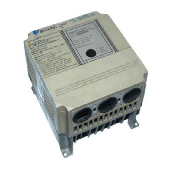
YASKAWA AC Drive Option
Braking unit,
Braking resistor unit
Installation Manual
BRAKING UNIT CDBR-
BRAKING RESISTOR UNIT LKEB-
To properly use the product, read this manual thoroughly and retain
for easy reference, inspection, and maintenance. Ensure the end user
receives this manual.
安川インバータオプション
制動ユニット,制動抵抗器ユニット
取扱説明書
制動ユニット
CDBR-
LKEB-
制動抵抗器ユニット
製品を安全にお使い頂くために,本書を必ずお読みください。
また,本書をお手元に保管していただくとともに,最終的に本製品をご使用になる
ユーザー様のお手元に確実に届けられるよう,お取り計らい願います。
MANUAL NO. TOBP C720600 00F
Advertisement
Table of Contents

Subscribe to Our Youtube Channel
Related Manuals for YASKAWA CDBR Series


Summary of Contents for YASKAWA CDBR Series
- Page 1 YASKAWA AC Drive Option Braking unit, Braking resistor unit Installation Manual BRAKING UNIT CDBR- BRAKING RESISTOR UNIT LKEB- To properly use the product, read this manual thoroughly and retain for easy reference, inspection, and maintenance. Ensure the end user receives this manual.
- Page 2 Inverters to which the braking resistor unit and braking unit can be con- nected are of the following series: • YASKAWA AC Drive 1000 Series • Varispeed Series Wiring sequence should shut off power to the drive when a braking...
- Page 3 S To order a copy of this manual, if your copy has been damaged or lost, contact your YASKAWA representative. S YASKAWA is not responsible for any modification of the product made by the user since that will void your guarantee.
-
Page 4: Notes For Operation
NOTES FOR SAFE OPERATION Read this instruction manual thoroughly before installation, operation, maintenance or inspection of the braking unit and the braking resistor unit. In this manual, NOTES FOR SAFE OPERATION are classified as “WARNING” or “CAUTION.” WARNING Indicates a potentially hazardous situation which, if not avoided, could result in death or serious injury to personnel. - Page 6 WIRING WARNING (Ref. page) • Only commence wiring after verifying that the power sup- ply is turned OFF. Failure to observe this warning can result in an electrical shock or a fire. • High voltage exists at all terminals of braking unit and braking resistor unit.
- Page 7 CAUTION (Ref. page) S Verify that the rated voltage of the braking unit and the braking resistor unit coincides with the AC power supply voltage. Failure to observe this caution can result in personal injury or a fire. S Do not perform a withstand voltage test of the braking unit and braking resistor unit.
- Page 8 OPERATION WARNING (Ref. page) S Only turn ON the input power supply after replacing the front cover. Do not remove the cover while current is flowing. Failure to observe this warning can result in an electrical shock. CAUTION (Ref. page) S Never touch the heatsink or discharging resistor since the temperature is very high.
- Page 10 CAUTION (Ref. page) S The control PC board employs CMOS ICs. Do not touch the CMOS elements. They are easily damaged by static electricity. S Do not connect or disconnect wires or connectors while power is applied to the circuit. Failure to observe this caution can result in personal injury.
- Page 11 WARNING INDICATION A warning label is displayed on the front cover of the braking unit, as shown below. Follow these instructions when handling the braking unit and the braking resistor unit. Warning Indication Example of Braking Unit Model CDBR−4045B...
- Page 12 Warning Indication...
-
Page 13: Table Of Contents
CONTENTS NOTES FOR OPERATION - - - - - - - - - - - - - - - - - - - - - - - - - - - - - - - - - - 5 1 RECEIVING - - - - - - - - - - - - - - - - - - - - - - - - - - - - - - - - - - - 15 1.1 NAMEPLATE - - - - - - - - - - - - - - - - - - - - - - - - - - - - - - - - - 15 2 INSTALLATION - - - - - - - - - - - - - - - - - - - - - - - - - - - - - - - - 16 2.1 LOCATION - - - - - - - - - - - - - - - - - - - - - - - - - - - - - - - - - - - 16... -
Page 14: Receiving
The braking resistor unit and braking unit have been put through severe tests at the factory before shipment. After unpacking, however, check and see the follow- ing. If any malfunctions are found, contact your YASKAWA representative. • Their nameplate data meet your requirements. -
Page 15: Installation
2 INSTALLATION 2.1 LOCATION If the units are temporarily stored or machine stops for an extended length of time, the following precautions should be taken. Store the units at pollution level 2 or less (UL standard) and under the following conditions. •... - Page 16 2 INSTALLATION • Install the units in the directions shown in Figs. 1 to 8. There will be no problem if they are installed vertically. 4−M4 MTG HOLE 2.83 (72) 2.73 (66.5) 1.5 (38) 1.5 (38) 4.51 (114.5) 5.04 (128) 1.18 (30) 1.18 (30) OR MORE...
- Page 17 4−M6 3.94 (100) MTG HOLE MAIN CIRCUIT TERMINAL M4 2.30 3−LEAD WIRE (58.5) OUTLET 1.10 (28) DIA RUBBER BUSH 1.97 (50) 3.94 (100) 6.57 (167) 5.51 (140) 1.18 (30) 1.18 (30) OR MORE OR MORE Fig. 2 Braking Unit Dimensions in inches (mm) CDBR−5037B...
- Page 18 2 INSTALLATION 4−M6 5.51 (140) MTG HOLE MAIN CIRCUIT TERMINAL M5 WIRE OUTLET 1.10 (28) 3.86 (98) DIA RUBBER BUSH 2−LEAD WIRE OUTLET 1.38 (35) DIA RUBBER BUSH 3.94 (100) 4.37 (111) 2.32 1.97 (50) (59) 6.14 (156) 5.51 (140) 7.09 (180) 7.87 (200) 1.18 (30)
- Page 19 4−M6 5.51 (140) MTG HOLE MAIN CIRCUIT WIRE OUTLET 1.10 (28) TERMINAL M6 4.09 DIA RUBBER BUSH (104) 2−LEAD WIRE OUTLET 1.38 (35) DIA RUBBER BUSH 3.94 (100) 4.37 (111) 2.32 1.97 (50) (59) 5.51 (140) 6.14 (156) 7.09 (180) 7.87 (200) 1.18 (30) 1.18 (30)
- Page 20 2. INSTALLATION 4−M6 7.09 (180) MTG HOLE MAIN CIRCUIT WIRE OUTLET 1.10 (28) TERMINAL M5 3.86 (98) DIA RUBBER BUSH 2−LEAD WIRE OUTLET 1.38 (35) DIA RUBBER BUSH 5.45 (138.5) 4.37 (111) 1.97 (50) 2.70 (68.5) 7.09 (180) 6.14 (156) 8.66 (220) 7.87 (200) 1.18 (30)
- Page 21 4−M6 8.27 (210) MTG HOLE MAIN CIRCUIT WIRE OUTLET 1.10 (28) TERMINAL M6 4.09 DIA RUBBER BUSH (104) 2−LEAD WIRE OUTLET 1.38 (35) DIA RUBBER BUSH 6.16 (156.5) 4.37 (111) 1.97 (50) 4.67 (118.5) 8.27 (210) 6.14 (156) 9.84 (250) 7.87 (200) 1.18 (30) 1.18 (30)
- Page 22 2 INSTALLATION Braking Resistor Dimensions in inches (mm) Unit Model (LKEB- ) 20P7 4.13 (105) 10.83 (275) 1.97 (50) 10.24 (260) 21P5 5.12 (130) 13.78 (350) 2.95 (75) 13.19 (335) 22P2 5.12 (130) 13.78 (350) 2.95 (75) 13.19 (335) 23P7 5.12 (130) 13.78 (350) 2.95 (75)
- Page 23 Dimensions in inches (mm) Braking Resistor Unit Model (LKEB- ) 2011 10.48 (266) 21.38 (543) 9.69 (246) 13.39 (340) 2015 14.02 (356) 21.38 (543) 13.23 (336) 13.39 (340) 2018 17.56 (446) 21.38 (543) 16.77 (426) 13.39 (340) 2022 17.56 (446) 21.38 (543) 16.77 (426) 13.39 (340) 4011 13.78 (350) 16.22 (412) 12.99 (330) 12.80 (325) 4015...
-
Page 24: Replacement Of Conventional Braking Units With New Units
2.3 REPLACEMENT OF CONVENTIONAL BRAKING UNITS WITH NEW UNITS To replace conventional braking units (models CDBR-2015, -2022, -4030, -4045) with new units (CDBR-2015B, -2015C, -2022B, -2022C, -4030B, -4045B), an exclusive-use attachment is required. Contact your YASKAWA representative. 4−M6 MTG HOLE ATTACHMENT 0.28(7) 3.94 (100) - Page 25 The main circuit terminal symbols are different between conventional models and new models. Refer to the following table. Table 1 Main Circuit Terminal Symbols New Models Conventional Models Example: CDBR-2015B, Example: CDBR-2015 -2015C...
-
Page 26: Wiring
3 WIRING 3 WIRING 3.1 REMOVING AND REPLACING THE COVERS OF THE BRAKING UNIT (MODELS CDBR-2015B, -2015C, -2022B, -2022C,-4030B, -4045B) Romoving and Replacing the Terminal Cover For removing, grasp the terminal cover at on borh sides and then lift in the direciton of . -
Page 27: Section Names
3.2 SECTION NAMES Figs. 10, 11 and 12 show appearance and each section name of braking unit and braking resistor unit respectively. Thermal overload relay protects the braking resistor unit for models LKEB-20P7 to -27P5 and -40P7 to -4015. Thermal protector protects the braking resistor unit for models LKEB-2011 to -2022 and -4018 to -4045. - Page 28 3 WIRING Top Side Thermal Overload Relay (Automatically Reset) Control Circuit Terminals B P 1 2 Lead Wire Outlet Bottom Side (Rubber Bush) Fig. 11 Braking Resistor Unit Model LKEB-20P7 SPEC: B (Front Cover Removed) Note: 1. External terminals for SPEC: B models LKEB- 20P7 and 40P7 are located up to 20 mm further inside the unit when compared to the same models for SPEC: A.
- Page 29 Resistor Thermal Overload Protector Lead Wire Outlet Control Circuit Terminals (Rubber Bush) B, P, 1, 2 Fig. 12 Braking Resistor Unit Model LKEB−2022 (Front Cover Removed)
-
Page 30: Circuits And Wiring Specifications
3 WIRING 3.3 CIRCUITS AND WIRING SPECIFICATIONS Table 2 Circuits and Wiring Specifications Wire Max. Size Termi- Terminal Name Circuit Wire Type Torque nals Screw lb.in (N·m) Braking Unit 12-10 Main (Models CDBR- (3.5-5.5) 2015B, -2015C 13.3 (1.50) -2022B, -2022C Con- 1 2 3 18-14... -
Page 31: Wiring Precautions
3.4 WIRING PRECAUTIONS Wiring Leading-in Method Lead in the wire through the knockout hole on the unit bottom. Since the knockout hole is provided with a rubber bush, cut the rubber bush central crosswise with a blade and lead the wire through. Separation from Signal Lines Since strong noise component is superimposed on the braking resistor unit and braking unit wiring, separate the units from signal lines which are weak... -
Page 32: Interconnection
Be sure to connect braking resistors or braking resistor units to the braking units. Connect only braking resistors or Braking Resistor Units (LKEB-XXXX) to Braking Units. 1. If using another braking resistor instead of YASKAWA braking resistor unit, wiring sequence should shut off power to the drive NOTE... - Page 34 3 WIRING...
- Page 36 3 WIRING...
- Page 38 3 WIRING...
-
Page 40: Operation
4. OPERATION OPERATION 4.1 ADJUSTMENT The braking resistor unit and braking unit do not have to be adjusted. Especially, do not readjust the braking unit except in the case described in Par. 4.2, “Power Supply Voltage Selection Connector Setting.” 4.2 POWER SUPPLY VOLTAGE SELECTION CON- NECTOR SETTING It may be necessary to select power supply voltage selection connector for braking unit according to main circuit power supply type. - Page 41 200 V class 200 V 208 V 220 V 230 V 400 V class 380 V 400 V 415 V 440 V 460 V Fig. 21 Braking Unit Power Supply Voltage Selection (Models CDBR-2015B, -2015C, -2022B, -2022C, -4030B, -4045B, Terminal Cover and Indicating Cover Removed)
- Page 42 4 OPERATION class class 200 V 400 V 380 V 200 V 400 V 208 V 415 V 220 V 440 V 230 V 460 V class 575 V 500 V 575 V Fig. 22 Braking Unit Power Supply Voltage Selection (Models CDBR-2045B, -2110B, -4090B, -5037B, -5110B, -5300B, Indicating Cover Removed) Table 3 Power Supply Voltage Selection Connector and Braking Start Voltage...
-
Page 43: Setting
4.3 MASTER/SLAVE SELECTION CONNECTOR SETTING Selection Connector Setting MASTER side is selected prior to shipment. Use the units without changing the setting. SLAVE side is selected when more than one braking unit is combined to use and braking start levels must coincide. Refer to Par. 4.4, “Parallel Connection of Brak- ing Unit”... -
Page 44: Operation
4 OPERATION Braking Resistor Braking Resistor Braking Resistor Overheat Contact Overheat Contact Overheat Contact (Thermal Relay Trip Contact) (Thermal Relay Trip Contact) (Thermal Relay Trip Contact) − Braking Braking Braking Resistor Resistor Resistor Unit Unit Unit − 0 − − −... -
Page 45: Troubleshooting
5 TROUBLESHOOTING Only authorized personnel should be permitted to perform maintenance and inspections or replace parts. Fault Status Cause Corrective Action • Without braking unit Replace the inverter. Inverter built-in main circuit dis- charging transistor short circuited Braking resistor • With braking unit unit overload relay (or thermal over- Replace the unit. -
Page 46: Specifications
6 SPECIFICATIONS 6 SPECIFICATIONS 6.1 BRAKING UNIT AND BRAKING RESISTOR UNIT APPLICATION LIST The applicable braking unit and braking resistor unit models differ depending on the inverter model. Refer to the catalog of the relevant inverter. Example: 200-V Class Inverter Model CIMR-G5 Inverter Braking Unit Braking Resistor Unit... - Page 47 Example: 400−V Class Inverter Model CIMR−G5 Approx. Inverter Braking Unit Braking Resistor Unit Braking Braking Max Applicable Model Model Torque Resistor Spec. Unit Unit Motor Capacity (10%ED) (CDBR (LKEB Q’ty Q’ty (per unit) HP(kW) − j) − j) 0.5 (0.4) −...
-
Page 48: Braking Unit For 575V Class Application List
6 SPECIFICATIONS 6.2 BRAKING UNIT FOR 575V CLASS APPLICATION LIST Example: 575-V Class Inverter Model CIMR-G5 Inverter Braking Unit Braking Resistor Unit Approx. Braking Max Applicable Torque Model Motor Capacity Unit Q’ty Resistor Spec. (10%ED) (CDBR- ) HP(kW) 5 (3.7) –... -
Page 49: List Of Applicable/Not Applicable Combinations With Conventional Models (Vs-616Hii/H3, Vs-616Gii/G3, Vs-676)
6.3 LIST OF APPLICABLE/NOT APPLICABLE COMBINA- TIONS WITH CONVENTIONAL MODELS (VS−616HII/ H3, VS−616GII/G3, VS−676) Applicable/ Conventional Braking Braking Re- Not Appli- Remarks Model Unit sistor Unit cable VS−616HII/H3 Model See connection exam- LKEB−20P7 VS−616GII/G3 Applicable − ples of Fig 14. etc. -
Page 50: Braking Unit Specifications
6 SPECIFICATIONS 6.4 BRAKING UNIT SPECIFICATIONS 200V to 300V 380V to 460V 500V to 575V 2015 2022 Braking Unit Model 2045 2110 4030 4045 4090 4220 5037 5110 5300 CDBR- 2015 2022 Applicable Motor Output HP (15) (22) (45) (110) (30) (45) (90) -
Page 51: Braking Resistor Unit Specifications
6.5 BRAKING RESISTOR UNIT SPECIFICATIONS Allowable Allowable Model Average Average Allowable (LKEB Specifications Dissipated Current Ambient Power (Effective Value) Temperature 20P7B 70W 200Ω 0.39 21P5B 260W 100Ω 0.77 22P2B 260W 70Ω 23P7B 390W 40Ω 25P5B 520W 30Ω 27P5B 780W 20Ω 230V 2011 2400W 13.6Ω... -
Page 52: Models And Code Nos. Of Braking Unit And Braking Resistor Unit
6 SPECIFICATIONS 6.6 MODELS AND CODE NOS. OF BRAKING UNIT AND BRAKING RESISTOR UNIT Braking Unit Inverter Model Code No. Voltage HP (kW) CDBR-2015B 72600-R2150B 20 (15) CDBR-2015C 72600-R2150C CDBR-2022B 72600-R2220B 200 to 30 (22) 230 V CDBR-2022C 72600-R2220C 60 (45) CDBR-2045B 72600-R2450B 150 (110) - Page 53 Braking Resistor Unit Inverter Resistor Spec. Model Code No. (per unit) Voltage HP(kW) 1 (0.75) 70W 200Ω LKEB-20P7 72600-K2P70B 2 (1.5) 260W 100Ω LKEB-21P5 72600-K2010B 3 (2.2) 260W 70Ω LKEB-22P2 72600-K2020B 5 (3.7) 390W 40Ω LKEB-23P7 72600-K2030B 7.5 (5.5) 520W 30Ω LKEB-25P5 72600-K2050B 200 to...
- Page 54 Phone: 81-3-5402-4502 Fax: 81-3-5402-4580 http://www.yaskawa.co.jp YASKAWA AMERICA, INC. 2121 Norman Drive South, Waukegan, IL 60085, U.S.A. Phone: 1-800-YASKAWA (927-5292) or 1-847-887-7000 Fax: 1-847-887-7310 http://www.yaskawa.com YASKAWA ELÉTRICO DO BRASIL LTDA. Avenida Piraporinha 777, Diadema, São Paulo, 09950-000, Brasil Phone: 55-11-3585-1100 Fax: 55-11-3585-1187 http://www.yaskawa.com.br...
Need help?
Do you have a question about the CDBR Series and is the answer not in the manual?
Questions and answers