Table of Contents
Advertisement
Quick Links
Advertisement
Table of Contents

Related Manuals for Optronis CamPerform CoaxPress CP70-1-M-1000


Summary of Contents for Optronis CamPerform CoaxPress CP70-1-M-1000
- Page 1 CamPerform CP70-1-M/C-1000 CoaxPress Camera User Manual Ref. 1875-SU-01-F...
-
Page 3: Table Of Contents
Contents Revision General Declaration of conformity RoHS compliance Scope of delivery Optronis customer service Remark, Attention Precautions Camera Power Environmental Conditions General Precautions Camera Electrical Interface Auxiliary (Aux.) connector pinout Camera Power Indicator Lamp (LED) CoaxPress Data Channels Lens mount and handling... - Page 4 CamPerformCP70-1-M/C-1000 Ref. 1875-SU-01-F Page 2...
-
Page 5: Revision
Revision Firmware Date Description 11.03 August 2016 8bit, 12bit, Speed increase only in y-direction, not in x-direction. 11.08 October 2016 -Add micro-second counter and image counter -Add hot pixel correction -Add CoaXPress 1.1.1 compatibility -Add user flash setup capabilities -Add Gain CamPerformCP70-1-M/C-1000 Ref. -
Page 6: General
General Declaration of conformity Manufacturer: Optronis GmbH Address: Ludwigstr. 2, 77694 Kehl, Germany We certify and declare under our sole responsibility that the following apparatus Product: CP70-1-M-1000 CP70-1-C-1000 conform with the essential requirements of the EMC Directive 2014/30/EU, based on the following specifications applied:... -
Page 7: Scope Of Delivery
/FMG: FMount for Nikon G-Lens series CoaxPress: up to 6,25GBit/channel, 4 channels Synchronisation Adapter cable Programming cable (USB2) for firmware update (Option) User Manual (CD-ROM) Optronis customer service Optronis GmbH Ludwigstr. 2 77694 Kehl Germany Tel: +49 (0) 7851 9126 0... -
Page 8: Remark, Attention
Remark, Attention This user manual is compliant with the firmware version v. 11.03 of the camera. The following signs are used in the user manual Remarks and additional information Attention Precautions Camera Power Please use Power over CoaxPress or as an option the CP70-1-M/C-1000 camera power supply (not included in shipment). -
Page 9: General Precautions
General Precautions Read the user manual carefully before using the camera. Do not orientate the optical input of the camera to direct sunlight. Keep the camera free protected from dirt, dust, grease and water. Make sure that all the connecting cables are in good condition. Defective cables have to be replaced. -
Page 10: Camera
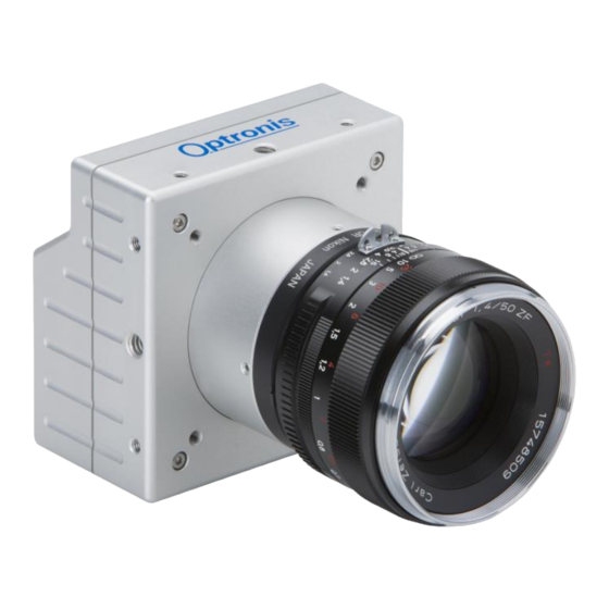
Camera 1: Camera housing 2: Mounting holes 2x M4x6mm 1x ¼ ``x6mm 3: Lens mount (Nikon-F) 4: lens (Nikon-F compatible, Option) 5: electrical interface (back side) 6: Mounting holes 4x M4x6mm CamPerformCP70-1-M/C-1000 Ref. 1875-SU-01-F Page 8... -
Page 11: Electrical Interface
1: CoaxPress Channels 2: Power Connector 3: Auxiliary Connector 4: Indicator Lamp (LED) Electrical Interface Camera (Pwr.) connector type: Hirose HR10A-7R-6S Cable Connector: Hirose HR10A-7R-6P CamPerformCP70-1-M/C-1000 Ref. 1875-SU-01-F Page 9... -
Page 12: Auxiliary (Aux.) Connector Pinout
Auxiliary (Aux.) connector pinout Auxiliary (Aux.) connector pinout Description External Synchronisation Input Sync. In TTL level: <0,8Volt (low) > 2 Volt (high) reserved External Synchronisation Output Sync. Out (TTL level @ high impedance, 0 to 2 Volt @ 50 Ohms ) 4+5+6 Sync. - Page 13 is in between 0 (low level) to ~4 Volts (high level). SyncOut voltage limit ranges from 0 Volt to + 5 Volts. Voltages applied beyond these limits may damage the SyncOut Output. The Auxiliary connector may also be used to update the firmware of the camera.
-
Page 14: Camera Power
Camera Power Figure: CP70-1-M/C-1000 back view Camera (Pwr.) connector type: Hirose HR10A-7R-4S Cable Connector: Hirose HR10A-7R-4P Power (Pwr.) connector pinout Description DC Power +24Volt +/-5% (Ripple < 200mV) Inrush Current ~0,6A Power Ground Alternatively Power over CoaxPress (PoCXP) should be used. Indicator Lamp (LED) CamPerformCP70-1-M/C-1000 Ref. -
Page 15: Coaxpress Data Channels
State Indication No power System booting Solid orange Powered, but nothing connected Slow pulse red (only for power over power connector) Link detection in progress, Fast flash green PoCXP active Linkt detection in progress, Fast flash orange PoCXP not in use Camera / Grabber incompatible, Slow flash alternate red / green PoCXP active... -
Page 16: Lens Mount And Handling
Lens mount and handling Nikon F-Mount adapter Camera housing lens-holder silver clip Nikon F-Mount adapter Figure: Camera with Nikon F-Mount adapter To mount the lens, it has to be positioned on the lens-holder in a way, that the back surface of the lens is completely attached to the surface of the lens- holder. - Page 17 lens-holder reference lens-reference lens-reference lens-holder reference lens unlocked lens locked To unmount the lens, pull back first the silver clip in order to unlock the lens as shown below. Then (the silver clip has still to be pulled back) turn the lens clockwise until the lens is unmounted completely.
-
Page 18: C-Mount Adapter
C-Mount adapter To mount the C-Mount lens, unscrew the protective cover anti-clockwise and mount the C-Mount lens into the lens holder. To unmount the lens, unscrew the C-Mount lens anti-clockwise. Important features The CamPerform CP70-1-M/C-1000 CoaxPress cameras are high frame rate CMOS area scan camera that are designed for industrial use. -
Page 19: Maximum Frame Rate (@ Internal Synchronisation)
Maximum Frame rate (@ internal synchronisation) Max. Frame Rate Examples (8bit): Pixel resolution x Pixel resolution y Max. Frame Rate CoaxPress labeling (Pixel) (Pixel) (fps) CXP6, BNC 4x 1280 1024 1051 CXP6, BNC 4x 2839 CXP6, BNC 4x 5252 CXP6, BNC 4x 10208 (Max. - Page 20 Calculation of Maximum Frame Rate at CXP6 BNC 4x in 12bits mode: For X> 960 : 1000000/ [0.922222*(SizeY+4)+2.62] For X<=960 : 1000000/ [0.722222*(SizeY+4)+2.62] Calculation of Maximum Exposure Time in 12bits mode: Exposure Time Max. = 1/Framerate – 2 us = 949 usec Min.
-
Page 21: Frame Rate (@ External Synchronisation)
Frame Rate (@ external synchronisation) For external synchronisation please apply a TTL signal to the Sync In and Sync Out BNC adapter of the adapter cable (scope of delivery). External synchronisation may be operated in level detection mode. Please see the external synchronisation timing for more information about resulting frame rates and exposure times. -
Page 22: Technical Data
Technical Data General Power Source PoCXP Alternatively: + 24 Volt +/. 5% DC < 200mV ripple Power approx. 8,5 Watt Pixel Number 1280x1024 Pixel size 6,6 µm x 6,6 µm Acitve area 8,448 mm x 6,758 mm Sensor responsitivity 9,6 Volt/lux.s Shutter Global Minimum Ambient... -
Page 23: Spectral Response / Transmittance
Spectral Response / Transmittance Spectral response (Monochrome Sensor) CamPerformCP70-1-M/C-1000 Ref. 1875-SU-01-F Page 21... -
Page 24: Mechanical Dimensions
Mechanical Dimensions F-Mount Lens (/FM) CamPerformCP70-1-M/C-1000 Ref. 1875-SU-01-F Page 22... - Page 25 Figure : Side View (all dimensions in mm) Screw threads in socket: M4 min. 6 mm depth 1 x ¼ `` min. 6 mm depth (in the middle) CamPerformCP70-1-M/C-1000 Ref. 1875-SU-01-F Page 23...
-
Page 26: Synchronisation Input Schematics
Synchronisation Input schematics Figure: SyncIn Schematics (for illustration only) Synchronisation Output schematics Figure: SyncOut Schematics (for illustration only) CamPerformCP70-1-M/C-1000 Ref. 1875-SU-01-F Page 24... -
Page 27: Internal Synchronisation Timing
Internal Synchronisation Timing Internal Sync Exposure T1: Exposure time, selected by software T2: Frame Interval (1/Frame Rate), selected by software Synchronisation Output Logic 1 during Exposure Time (T1) CamPerformCP70-1-M/C-1000 Ref. 1875-SU-01-F Page 25... -
Page 28: External Synchronisation Timing
External Synchronisation Timing Synchronisation Input “level detection” positive level: Sync In Exposure Sync In rising level to Exposure Delay: ~ 2.7usec +/- 500 nsec typical T1: Exposure time T2: 1/Frame Rate T3: 1/Maximum Frame Rate (limited by readout of the sensor) depends on frame format 1/T2 has to be larger than 20 fps Synchronisation Output “level detection”... -
Page 29: Camera Firmware Update
Camera firmware update Camera firmware update is available through the USB programming cable and the CXP_Flash_Consumer software (located in the CXPFlash_Setup folder) delivered with the camera. Please go through the following steps : 1) Switch OFF camera 2) Connect USB cable to PC and camera Aux. input. 3) Install USB driver on PC if it is not already done. - Page 30 Wait until finished. 6) Click on Exit. 7) Switch OFF camera and switch ON camera. CamPerformCP70-1-M/C-1000 Ref. 1875-SU-01-F Page 28...
-
Page 31: Camera Mapping
Camera mapping This part is an extract of the GenICam xml file. DeviceVendorName Name of the manufacturer of the device. DeviceModelName This feature provides the model of the device DeviceManufacturerInfo This feature provides extended manufacturer information about the device DeviceVersion This feature provides the version of the device DeviceFirmwareVersion Version of the firmware in the device... - Page 32 Height This feature represents the actual image height expelled by the camera (in pixels). OffsetX Horizontal offset from the origin to the area of interest (in pixels) OffsetY Vertical offset from the origin to the area of interest (in pixels) PixelFormat This feature indicates the format of the pixel to use during the acquisition AcquisitionMode...
- Page 33 Return 0x1 for a color sensor and 0x0 for a monochrom sensor AddCounterInformation When set to ‘Yes’, counter informations are integrated in the first pixels of every transferred frame: 16 first bits contain an image counter (incrementing with every frame transferred) 24 next bits contain a micro-second precision counter that indicates the time when exposure has started.
-
Page 34: GenCam
Optronis ships together with the CP70-1-M/C-1000 camera a XML file that is Gen<i>Cam compatible. The XML file follows the SNFC (Standard Features Naming Convention). Please ask, if needed, the Optronis customer service for the availability of this XML file. CamPerformCP70-1-M/C-1000 Ref.
Need help?
Do you have a question about the CamPerform CoaxPress CP70-1-M-1000 and is the answer not in the manual?
Questions and answers